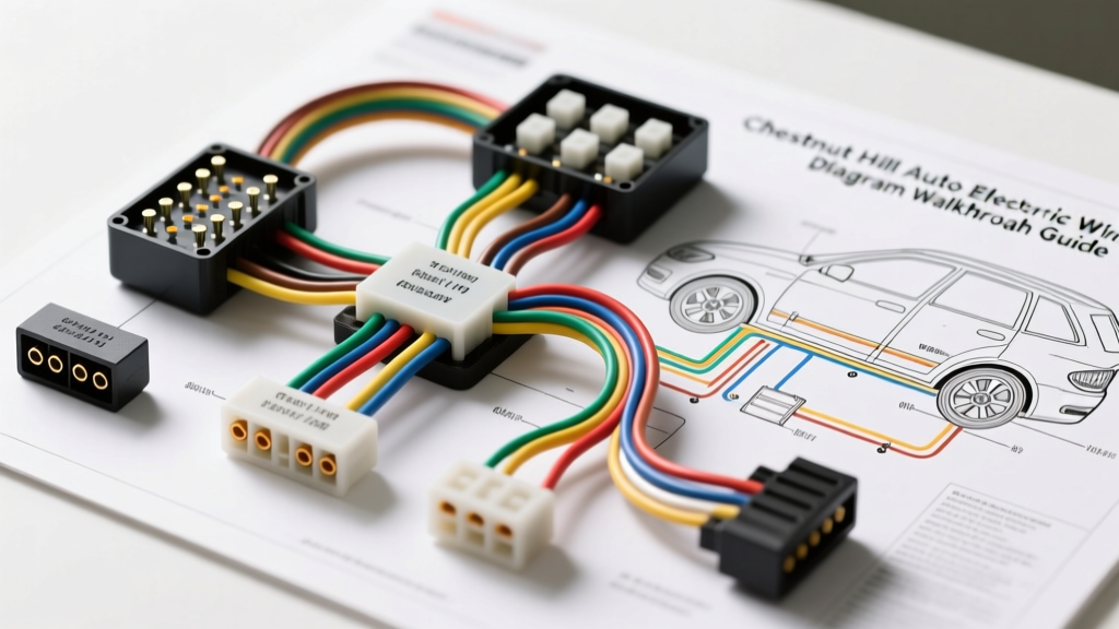
Mastering the Schematic: The Chestnut Hill Auto Electric Walkthrough Method
When diagnosing late-model vehicle electrical architectures, guessing is not a strategy. Elite diagnostic centers, operating with the meticulous Chestnut Hill Auto Electric wiring diagram walkthrough methodology, approach OEM schematics not merely as maps, but as logical flowcharts. Modern vehicles utilize multiplexed networks, smart power distribution, and pulse-width modulated (PWM) charging systems that require a fundamental understanding of electrical theory combined with precise diagram tracing. This comprehensive guide breaks down the professional-grade workflow for navigating complex wiring diagrams, focusing on a late-model Smart Alternator and Body Control Module (BCM) integration circuit.
Phase 1: Decoding the Schematic Grid and Power Distribution
Before tracing a single wire, a professional technician must understand the layout of the OEM service manual. Most manufacturer diagrams utilize a grid coordinate system (e.g., A1 through F8) to help you locate specific connectors and splices across multi-page PDFs. The Chestnut Hill Auto Electric standard dictates that you never begin testing a circuit without first locating the primary Power Distribution Center (PDC) and identifying the upstream protection devices.
Analyzing the PDC and Mega-Fuses
In a modern smart charging system, the alternator's main output (B+ terminal) is typically protected by a 150A to 250A Mega-Fuse or ANL fuse located in the under-hood PDC. This circuit utilizes heavy-gauge wiring to handle the high amperage required to recharge the battery and supply the vehicle's baseline electrical load.
- Wire Gauge: 2 AWG to 4 AWG (Stranded copper, typically Red or Red with a Black stripe).
- Routing: Directly from the alternator B+ stud to the battery positive terminal or main PDC bus bar.
- Connection Type: M8 or M10 ring terminal, torqued to manufacturer specifications (usually 10-15 Nm) to prevent high-resistance hot spots.
If a vehicle presents with a 'Battery Not Charging' message, the first step in the diagram walkthrough is verifying voltage on both sides of the Mega-Fuse with the engine running. A reading of 14.2V on the battery side and 0V on the alternator side indicates a blown high-amperage fuse or a severed 2 AWG cable.
Phase 2: Tracing the LIN Bus Smart Alternator Circuit
Unlike older vehicles that used a simple 12V ignition exciter wire and a discrete sense wire, modern alternators are controlled via a Local Interconnect Network (LIN) bus. The LIN bus is a single-wire, low-speed serial communication network that allows the Body Control Module (BCM) or Powertrain Control Module (PCM) to dictate exact voltage output based on real-time electrical demands and battery temperature.
Step-by-Step Pinout Walkthrough
Let us trace the control circuit from the BCM to the alternator voltage regulator, a common focal point in advanced auto electrical diagnostics.
| Circuit Function | Wire Color Code | AWG Size | Connector / Pin Location |
|---|---|---|---|
| Alternator B+ Feed | Red (RD) | 2 AWG | Alternator Stud / Battery Pos |
| LIN Bus Control Signal | Purple w/ White Trace (PU/WT) | 22 AWG | Alternator C1 Pin 2 to BCM X2 Pin 42 |
| Ignition Sense / Wake-Up | Yellow w/ Red Trace (YE/RD) | 18 AWG | Alternator C1 Pin 1 to PDC Fuse 14 |
| Main Chassis Ground | Black (BK) | 6 AWG | G104 (Left Strut Tower Ground) |
Verifying the Wake-Up Signal
Pin 1 on the alternator connector (C1) is the ignition sense circuit. When the ignition is turned to the 'ON' position, the PDC closes a relay, sending 12V through an 18 AWG Yellow/Red wire. This voltage 'wakes up' the internal voltage regulator. If this circuit is open, the alternator will not produce output, even if the LIN bus is functioning perfectly. Using a digital multimeter (DMM), probe the back of the alternator connector for 12.0V to 12.6V with the key on, engine off (KOEO).
Phase 3: Oscilloscope Diagnostics on the LIN Bus
A standard DMM will only show an 'average' voltage on a LIN bus wire (typically 7V to 10V), which is insufficient for verifying data integrity. The Chestnut Hill Auto Electric diagnostic protocol requires the use of a digital storage oscilloscope (DSO) to view the actual square wave communication between the BCM and the alternator.
Setting Up the DSO
- Channel A: Connect to the LIN bus wire (Purple/White) at the alternator C1 Pin 2 using a piercing probe or back-pinning tool to avoid damaging the 22 AWG wire.
- Timebase: Set to 50 µs/div to 100 µs/div to capture the 19.2 kbps baud rate signal.
- Voltage Scale: Set to 2V/div or 5V/div.
- Trigger: Edge trigger, rising slope, set at 6V.
According to the SAE J2602 LIN Bus Specification, the bus idle state (recessive) should sit at battery voltage (approx. 12V-14V). When the BCM transmits a command (dominant state), the voltage should drop sharply to between 1.0V and 1.5V. If the waveform appears rounded, skewed, or fails to drop below 3V, you are likely dealing with high resistance in the 22 AWG wire, a failing internal regulator pull-up resistor, or electromagnetic interference (EMI) from improperly routed ignition coils.
Phase 4: Ground Path Verification and Voltage Drop Testing
Electrical current must return to its source. A failure in the ground circuit is responsible for over 60% of misdiagnosed alternator and BCM failures. The diagram indicates that the alternator case is grounded through the engine block, which is tied to the chassis via a heavy 6 AWG Black ground strap at location G104 (Left Strut Tower).
The Voltage Drop Test Protocol
Never rely on an ohmmeter to test a ground circuit; an ohmmeter uses less than 1 milliamp of current, which can easily pass through a single strand of frayed copper. A voltage drop test evaluates the circuit under a real-world load.
- Start the engine and turn on maximum electrical loads (headlights, rear defroster, HVAC blower on high).
- Set your DMM to DC Volts.
- Place the red probe on the alternator case (bare metal).
- Place the black probe on the battery negative terminal.
- Acceptable Limit: The reading must be 0.10V (100mV) or less. A reading of 0.25V or higher indicates severe corrosion at the G104 ground point or a degraded engine-to-chassis ground strap.
If the ground is compromised, the BCM will misinterpret the alternator's output voltage, often commanding the LIN bus to overcharge the battery to compensate for the perceived voltage drop, leading to boiled battery acid and blown BCM drivers.
Phase 5: Professional Wire Repair Standards
When the diagram walkthrough reveals a broken wire or corroded pin, the repair must match OEM standards. Twisting wires together and wrapping them in electrical tape is strictly prohibited. For 22 AWG LIN bus wires, technicians must use solder-seal heat shrink connectors or OEM-approved crimp-and-seal butt connectors. For high-amperage circuits like the 2 AWG B+ feed, ultrasonic welding or heavy-gauge hex-crimping with adhesive-lined marine-grade heat shrink is required to prevent moisture ingress and subsequent galvanic corrosion. For further reading on professional harness repair, refer to Haynes Auto Electrical Tutorials and OEM-specific wiring repair manuals.
Summary: The Diagnostic Mindset
A successful Chestnut Hill Auto Electric style wiring diagram walkthrough is about understanding the 'why' behind the circuit design. By systematically verifying the PDC protection, tracing the wake-up and LIN bus signals, validating data integrity with an oscilloscope, and stress-testing the ground paths under load, you eliminate guesswork. This methodical approach ensures accurate diagnostics, prevents unnecessary parts replacement, and restores the vehicle's complex electrical architecture to factory-operating parameters.