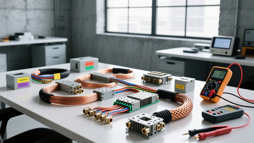
Introduction to Professional Auto Electrical Diagnostics
Modern vehicle electrical architecture has evolved far beyond simple 12-volt DC circuits and mechanical relays. Today's vehicles rely on multiplexed networks, including High-Speed CAN (Controller Area Network), Low-Speed CAN, LIN (Local Interconnect Network), and GMLAN. Diagnosing faults within these systems requires a fundamental shift in both tooling and methodology. When evaluating the cost and tool requirements of advanced diagnostics, many technicians and advanced DIYers look to established industry benchmarks, often referencing the rigorous diagnostic standards upheld by specialist shops like Williamson Auto Electric. Understanding what it takes to properly diagnose a parasitic draw, a PWM-controlled alternator fault, or a CAN-bus dropout is essential for determining whether to invest in professional-grade tooling or hand the keys over to a specialist.
The True Cost of Auto Electrical Troubleshooting
The most common mistake in auto electrical diagnosis is the 'parts cannon' approach—replacing components based on symptom guessing rather than empirical data. A professional auto electric shop operates on a model of high upfront tool investment and precise, time-efficient diagnostics. Below is a cost and tool requirements analysis comparing a typical DIY approach to a professional Williamson Auto Electric-style diagnostic workflow for a complex 'No-Crank / CAN-Bus Dropout' scenario.
| Category | DIY / General Mechanic Approach | Professional Auto Electric Specialist |
|---|---|---|
| Primary Tools | Test Light ($15), Basic DMM ($30) | Automotive Oscilloscope ($500+), True-RMS DMM ($400), Breakout Boxes ($250) |
| Diagnostic Method | Voltage checks at battery/starter; swapping relays; guessing BCM failure. | CAN-bus waveform analysis; voltage drop testing under load; LIN-bus duty cycle verification. |
| Time Invested | 8-15 hours (often unresolved) | 1.5 - 3 hours |
| Parts Replaced (Guessing) | Starter, Ignition Switch, BCM ($600 - $1,200) | Targeted repair: Chafed CAN-H wire or corroded X200 connector ($5 - $50 in materials) |
| Total Estimated Cost | $650 - $1,250+ (plus high frustration) | $250 - $450 (Shop Labor + precise materials) |
As the table illustrates, the 'Williamson Auto Electric' model of precision diagnostics actually saves the vehicle owner money in the long run by eliminating unnecessary parts replacement. However, for the DIYer, acquiring the necessary tooling represents a significant barrier to entry, making professional service highly cost-effective for network-level faults.
Essential Tool Requirements for Advanced Diagnostics
To meet professional auto electrical standards, specific tools are non-negotiable. Standard hardware store multimeters and test lights are not only inadequate; they can actively damage sensitive electronic control modules (ECMs).
1. True-RMS Digital Multimeter (DMM) with 10-Megohm Impedance
A standard DMM may not accurately read the RMS voltage of non-sinusoidal waveforms, such as the Pulse Width Modulated (PWM) signals used in modern alternator control or fuel injectors. Furthermore, a 10-Megohm input impedance is critical. Lower impedance meters can 'load' high-impedance sensor circuits, altering the voltage and potentially triggering false diagnostic trouble codes (DTCs). The Fluke 88V or 87V remains the industry standard for automotive DMMs due to their robust over-voltage protection and fast continuity beep.
2. Automotive Oscilloscope (Scope)
When a CAN-bus fault occurs, a DMM will only show an average voltage (e.g., 2.5V on CAN-High). It cannot reveal the underlying corruption. An automotive oscilloscope, such as those manufactured by Pico Technology, samples the circuit thousands of times per second, displaying the actual square-wave data packets. This allows a technician to see if a CAN-High wire is shorting to ground, shorting to CAN-Low, or suffering from termination resistor failures.
3. Proper Probing and Terminal Extraction Tools
Piercing wire insulation with a T-pin or test light probe introduces a pathway for moisture, leading to copper oxidation and eventual green rot (verdigris). Professional diagnostics require back-probing connectors using specialized probe pins or piercing probes only as an absolute last resort on non-data circuits. Additionally, terminal extraction tools for Deutsch DT series, GM Weather-Pack, and TE Connectivity AMP seals are mandatory for safely removing pins without destroying the connector housing.
Technical Case Study: GM Alternator LIN Bus Diagnostics
To understand the necessity of advanced tooling, consider the charging system on a modern General Motors vehicle (e.g., 2014-2020 Silverado equipped with a Delco Remy AD230 or AD244 alternator). Unlike older CS130 alternators that used simple L, I, S, and P terminals with basic 12V logic, the AD244 utilizes a single-wire LIN (Local Interconnect Network) bus to communicate with the Engine Control Module (ECM).
Pin Configuration and Wiring Specs
- Connector Type: 2-Way Female Metri-Pack 280 Series (Often only 1 or 2 cavities populated depending on exact RPO code).
- Pin A (LIN Bus): Typically a Gray or Gray/Black wire, 18 AWG (SAE J1128 GXL or TXL insulation).
- Signal Type: 125Hz PWM Signal, 0V to 12V square wave.
- B+ Output Terminal: M8 stud, requires 4 AWG to 1/0 AWG battery cable depending on routing length and alternator amperage (typically 130A-150A). Torque spec: 15-20 Nm.
The Diagnostic Process
If the vehicle is undercharging (stuck at 12.5V) or overcharging (15.2V+), a DIYer might test the Gray wire with a DMM. The DMM will likely read an average of 6V to 8V, leading the DIYer to incorrectly assume the wire is intact or that the alternator is 'partially working'.
A technician following the Williamson Auto Electric diagnostic protocol will connect an oscilloscope to the Gray wire using a non-piercing back-probe. The scope will reveal the 125Hz square wave. By analyzing the duty cycle of the waveform, the technician can determine if the ECM is commanding the correct field coil excitation. If the ECM commands a 85% duty cycle (high charge) but the alternator only outputs 13.0V, the fault lies internally within the alternator's voltage regulator or the carbon brushes. If the scope shows a flat 12V line with no PWM modulation, the ECM is not communicating, pointing to a network fault, a blown ECM fuse, or a severed 18 AWG Gray wire.
Advanced Parasitic Draw Analysis
Parasitic draws are notorious for causing dead batteries and misdiagnosed starters. The acceptable parasitic draw on modern vehicles with numerous keep-alive memory modules is typically under 50mA (0.050A) after the vehicle has entered 'sleep mode' (which can take up to 45 minutes on late-model European and domestic trucks).
The Voltage Drop Method vs. Ammeter Method
Breaking the battery circuit to insert a DMM in series (Ammeter method) is risky on modern cars. If a door is opened or a module wakes up while the meter is in the mA port, the internal fuse of the DMM will blow instantly. Furthermore, disconnecting the battery resets module sleep states, forcing the technician to wait another 45 minutes for the vehicle to go back to sleep.
Instead, professional auto electricians use the Voltage Drop across Fuses method. By measuring the millivolt (mV) drop across the two test points on top of a standard blade or Mega fuse, and referencing a fuse voltage drop chart, technicians can identify the exact circuit drawing current without ever disconnecting the battery or breaking the circuit. For example, a 10A ATO blade fuse showing a 1.5mV drop indicates a specific amperage draw that can be cross-referenced to identify a rogue BCM or infotainment amplifier.
Wire Repair and SAE Standards
When a fault is isolated to a physical wire break or chafe, the repair methodology is just as critical as the diagnosis. Twisting wires together and wrapping them in vinyl electrical tape is a guaranteed path to future failure. Professional shops adhere to SAE J1128 and OEM wiring standards.
- Splicing: Use only adhesive-lined, dual-wall heat shrink tubing with brass barrel crimps. Soldering is generally discouraged in high-vibration automotive environments because it creates a rigid point that can lead to work-hardening and wire fatigue failure just outside the solder joint.
- Wire Selection: Always use automotive-grade primary wire (GXL, TXL, or SXL) which features cross-linked polyethylene insulation rated for 125°C to 150°C. Never use PVC wire from a hardware store, as it will melt against exhaust components and degrade rapidly under-hood.
- Connector Sealing: When replacing terminals in a weather-sealed connector, the silicone mat seal (cavity plug) must be replaced if pierced or stretched, and dielectric grease must be applied to prevent galvanic corrosion between dissimilar metals.
Conclusion: Knowing Your Limits
The cost and tool requirements for proper auto electrical diagnosis are substantial. While a dedicated DIYer can justify the cost of a True-RMS DMM and basic current clamps for battery, starter, and simple relay diagnostics, network-level faults, LIN-bus alternator controls, and complex parasitic draws require oscilloscopes, breakout boxes, and deep architectural knowledge. Recognizing the threshold between basic circuit testing and advanced multiplexed network diagnostics is the hallmark of a smart technician. When the diagnostic path requires analyzing CAN-bus waveforms or decoding PWM duty cycles, relying on the established standards of a professional Williamson Auto Electric specialist is not an admission of defeat—it is the most cost-effective and reliable strategy for modern vehicle repair.