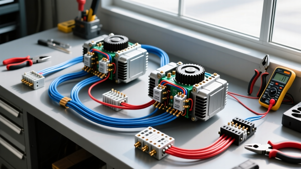
The Benchmark for Expedition Electrical Architecture
Modern overland and expedition vehicles demand massive electrical overhead. From 3000W inverter/chargers and 12V compressor fridges to high-lumen LED light bars and auxiliary air compressors, the factory 150A alternator is no longer sufficient. When benchmarking high-end expedition builds, the Sal's Auto Electric LLC methodology has become the gold standard for dual-alternator and lithium house bank integrations. Their approach prioritizes military-grade terminations, zero voltage-drop routing, and rigorous adherence to marine and heavy-duty SAE standards.
This guide details the exact upgrade and modification protocol for installing a secondary 250A alternator and a 400Ah Lithium Iron Phosphate (LiFePO4) house bank in a late-model heavy-duty truck (e.g., 2020+ Ford F-250 7.3L or Chevy 2500HD 6.6L). By following these high-amp wiring principles, you ensure that your auxiliary power system operates safely under extreme vibration, temperature fluctuations, and continuous high-load conditions.
Phase 1: Secondary Alternator Power Distribution
The foundation of any high-amp upgrade is the physical wiring between the secondary alternator's B+ terminal and the auxiliary battery bank. Standard copper wire is insufficient due to corrosion and strand breakage under engine vibration. The Sal's Auto Electric LLC standard mandates the use of SAE J1128 and SAE J1171 compliant fine-strand, tinned marine copper wire.
Wire Sizing and Voltage Drop Calculations
For a 250A continuous output alternator with a total positive and negative cable run of 16 feet, you must use 2/0 AWG welding wire. Using 1/0 AWG will result in a voltage drop exceeding 0.25V at peak load, which confuses the alternator's internal voltage regulator and causes premature stator burnout. The target voltage drop across the entire high-amp circuit must remain below 0.10V at maximum amperage.
- Positive Run: 2/0 AWG Tinned Copper (Red insulation), routed away from exhaust manifolds and steering shafts.
- Negative Run: 2/0 AWG Tinned Copper (Black insulation), bonded directly from the alternator housing to the auxiliary negative busbar.
- Protection: A 300A Class-T or ANL fuse must be installed on the positive cable within 7 inches of the auxiliary battery bank positive terminal, per ABYC E-11 guidelines.
Phase 2: High-Amp Cable Routing and Termination Standards
A wire is only as good as its termination. High-amperage circuits generate immense heat at points of high resistance. The Sal's Auto Electric LLC methodology strictly forbids soldering high-amp lugs, as solder can wick into the wire strands, creating a rigid section that snaps under engine vibration. Instead, use a hex-indent pneumatic or manual crimper with the exact 2/0 AWG die.
The Adhesive Heat-Shrink Protocol
After crimping, every termination must be sealed using 3:1 ratio adhesive-lined heat shrink. When heated, the inner thermoplastic adhesive melts and flows between the wire strands, creating a waterproof, oxygen-free seal that prevents galvanic corrosion. For alternator B+ terminals, use high-temp (125°C) polyolefin heat shrink to withstand under-hood radiant heat.
When tightening terminal lugs to busbars or battery posts, a calibrated torque wrench is mandatory. Overtightening stretches the copper and cracks the battery post; undertightening creates an arc-flash hazard.
Phase 3: Battery Isolation Manager (BIM) and BMS Pinouts
Connecting a LiFePO4 house bank directly to a lead-acid starting battery will destroy both batteries due to differing resting voltages and charging profiles. A Battery Isolation Manager (BIM) or advanced DC-DC charger is required. Below is the standard pinout configuration for integrating a smart BIM (such as the Blue Sea Systems 7622 or Sterling Power Pro Alt) with a LiFePO4 Battery Management System (BMS).
Smart BIM Control Wire Pinout
The control harness dictates when the BIM connects the two banks. The wiring must utilize 12 AWG stranded wire for the main relay coil power, and 18 AWG for sense circuits.
| BIM Pin | Wire Color | AWG | Connection / Function |
|---|---|---|---|
| Pin 1 (VCC) | Red | 12 AWG | Constant 12V+ from Starting Battery (Fused at 15A) |
| Pin 2 (IGN) | Yellow | 18 AWG | Ignition Sense (Taps into fuse box IGN circuit) |
| Pin 3 (GND) | Black | 12 AWG | Chassis Ground (Star-grounded to dedicated busbar) |
| Pin 4 (SENSE) | Blue | 18 AWG | Alternator Sense (Connected to Alternator B+ terminal) |
| Pin 5 (BMS) | White | 18 AWG | LiFePO4 BMS Charge Disconnect Relay Trigger |
Expert Note: The White BMS wire is critical. If the LiFePO4 BMS detects a high-voltage cell spike (typically >14.6V), it opens the internal MOSFETs. If the alternator is still pushing 250A when the BMS opens, the resulting voltage spike will instantly blow the alternator diodes. The White wire signals the BIM to drop the relay before the BMS opens, safely shedding the alternator load back to the starting battery.
Technical Specifications: Wiring & Crimp Standards
Adhering to strict torque and crimp specifications ensures longevity. The following chart outlines the mechanical requirements for high-amp expedition builds.
| Wire Gauge (AWG) | Max Continuous Amps | Crimp Die Type | Terminal Torque (3/8" Stud) |
|---|---|---|---|
| 4 AWG | 120A | Hex-Indent (Yellow) | 10 ft-lbs (120 in-lbs) |
| 1/0 AWG | 190A | Hex-Indent (Pink) | 12 ft-lbs (144 in-lbs) |
| 2/0 AWG | 250A | Hex-Indent (Black) | 15 ft-lbs (180 in-lbs) |
| 4/0 AWG | 350A | Hex-Indent (Purple) | 18 ft-lbs (216 in-lbs) |
Real-World Failure Modes & Diagnostics
Even with premium components, high-amp systems can exhibit faults if the underlying physics of the circuit are ignored. Use this diagnostic decision tree to troubleshoot common dual-alternator upgrade issues.
Symptom: High-Pitched Alternator Whine in Audio System
- Cause: Ground loop. The auxiliary battery negative and the audio amplifier ground are tied to different chassis points with varying resistance, causing audio signal cables to carry the return current.
- Fix: Implement a 'Star Ground' topology. Run all heavy negative cables (alternator, house bank, inverter) to a single, isolated, solid copper busbar bolted directly to the engine block or a cleaned, bare-metal chassis point. Never daisy-chain grounds.
Symptom: Secondary Alternator Output Drops to 40A After 10 Minutes
- Cause: Thermal throttling due to under-hood heat soak, or voltage drop on the alternator sense wire. If the sense wire reads 14.4V but the battery is actually at 13.8V due to a bad connection, the regulator prematurely tapers the charge.
- Fix: Verify the Blue Sense Wire (Pin 4) is terminated directly at the alternator B+ post, not at the battery. Ensure the alternator housing has a dedicated 4 AWG ground strap to the engine block to complete the sense circuit accurately.
Symptom: ANL Fuse Discolors and Melts Without Blowing
- Cause: Undersized fuse terminals or improper crimping on the fuse block lugs. Resistance at the fuse block generates localized heat (I²R losses).
- Fix: Replace standard brass fuse blocks with CNC-machined copper busbars plated in tin. Ensure the 2/0 AWG lugs mating to the ANL fuse are torqued to 15 ft-lbs.
Authoritative Standards and References
When designing high-current automotive and marine systems, adherence to established engineering standards is non-negotiable. The methodologies detailed above are derived from the following authoritative resources:
- SAE J1128 (Low Tension Primary Cable) - Defines the thermal and mechanical requirements for automotive wiring insulation and strand construction.
- ABYC E-11 / Blue Sea Systems Circuit Protection - The definitive guide for overcurrent protection placement, fuse sizing, and marine-grade DC wiring practices adapted for expedition vehicles.
- Victron Energy Wiring Unlimited - Comprehensive whitepaper on voltage drop calculations, lithium BMS integration, and high-amp DC busbar architectures.
By treating your vehicle's electrical system with the same rigor as a marine vessel, and applying the exacting standards championed by top-tier shops like Sal's Auto Electric LLC, you guarantee a reliable, safe, and high-performing power grid for any environment.