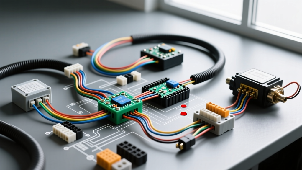
The Core Philosophy of Modern Auto Electric Training
When approaching a crank-no-start condition, novice technicians often fall into the trap of 'parts swapping' or relying on basic continuity tests. True auto electric training demands a systematic, step-by-step troubleshooting flow that evaluates circuits under load. Modern vehicle electrical architectures, particularly in late-model trucks like the GM EcoTec3 5.3L V8 (2014-2018), utilize complex PCM-controlled relay networks and high-amperage starter circuits that cannot be diagnosed with a simple test light.
This guide serves as an advanced masterclass in starter circuit diagnostics. We will bypass the guesswork and utilize a strict voltage-drop troubleshooting flow, referencing specific AWG wire sizes, ISO relay pinouts, and OEM torque specifications to isolate faults accurately.
The Flaw of Continuity Testing in High-Amperage Circuits
Before executing the troubleshooting flow, it is critical to understand why ohmmeters fail in starter circuit diagnostics. A standard digital multimeter (DMM) sends less than 1 milliamp of current through a circuit to measure resistance. If a 1/0 AWG battery cable has 38 out of 40 copper strands severed due to corrosion or physical trauma, the remaining two strands will still show near-zero ohms on a continuity test. However, when the starter draws 250+ amps, those two strands will act as a massive resistor, causing severe voltage drop and a no-crank condition. Voltage drop testing under load is the only valid method for verifying the integrity of high-amperage automotive wiring.
Phase 1: Visual & Mechanical Baseline Verification
Never connect a DMM until the physical baseline is verified. Electrical faults are frequently masked by poor mechanical connections.
- Battery State of Charge (SOC): Verify the battery is at minimum 12.4V (approx. 75% SOC). A starter requires massive amperage; a surface charge of 12.6V with low cold cranking amps (CCA) will skew voltage drop readings.
- Terminal Torque & Cleanliness: Inspect the top-post or side-post terminals. For GM top-post applications, the battery clamp bolt must be torqued to 15 Nm (11 lb-ft). Clean any copper sulfate (blue/green crust) using a baking soda solution and a wire brush.
- Cable Routing & AWG Verification: Ensure the positive cable is the OEM-specified 1/0 AWG and the negative ground strap is 2 AWG. Aftermarket replacements often use undersized 4 AWG wire to cut costs, which inherently causes voltage drop.
Phase 2: The Control Circuit Troubleshooting Flow
The starter solenoid requires a control signal to engage the Bendix drive and close the internal high-amperage contacts. In modern architectures, the ignition switch does not power the solenoid directly; it signals the PCM, which then grounds the starter relay.
ISO Mini Relay Pinout & Verification
Locate the starter relay in the underhood fuse block. Using a DMM, back-probe the relay socket to verify the control circuit flow.
| Pin Number | Function | Wire Color (Typical GM) | Expected Reading (Key in Crank) |
|---|---|---|---|
| Pin 30 | Constant B+ Feed | Red (10 AWG) | 12.2V - 12.6V (Battery Voltage) |
| Pin 86 | Ignition Run/Crank Feed | Pink (18 AWG) | 11.5V+ (During Crank) |
| Pin 85 | PCM Controlled Ground | Dark Green/White (18 AWG) | Less than 0.1V (When PCM pulls low) |
| Pin 87 | Starter Solenoid Feed | Purple (12 AWG) | 11.5V+ (Output to Solenoid) |
Troubleshooting Flow Step: If Pin 86 has 12V, and the PCM successfully grounds Pin 85, but Pin 87 outputs 0V, the relay coil is internally open. Replace the relay. If Pin 85 does not drop to ground, the PCM is inhibiting the crank request (check for immobilizer/theft deterrent DTCs or transmission range sensor misalignment).
Phase 3: The Power Circuit Voltage Drop Test
If the control circuit is verified and the starter solenoid clicks, but the engine fails to turn over (or turns over sluggishly), the fault lies in the high-amperage power circuit. You must perform a voltage drop test while the circuit is under load (i.e., while the key is held in the crank position).
Step-by-Step Positive Side Drop Test
- Set your DMM to DC Volts (20V scale).
- Place the Red probe directly on the battery positive post (not the clamp, the actual lead post).
- Place the Black probe directly on the starter B+ terminal stud (the large threaded post where the 1/0 AWG cable lands).
- Have an assistant turn the key to the CRANK position and hold it for 3 seconds.
- Record the maximum voltage reading. According to ASE certification standards, the total positive side voltage drop must not exceed 0.2V.
Step-by-Step Negative Side Drop Test
- Move the Red probe to the starter motor housing (bare metal, clean off any grease or paint).
- Move the Black probe to the battery negative post.
- Crank the engine and record the reading. The total negative side drop must also be under 0.2V.
Expert Insight: The Phantom Voltage Phenomenon
High-impedance DMMs (10 Megohm input) can read 'phantom voltage' on the control wire (Pin 87 to Solenoid) if the wire is broken but routed near other live harnesses. Capacitive coupling can trick the meter into showing 12V. Always use a low-impedance test light or a DMM with a Low-Z setting to verify control circuit voltage under a physical load.
Phase 4: Advanced Ground Path Verification
The starter motor grounds through its physical mounting to the engine block, and the engine block grounds to the chassis and battery via the 2 AWG ground strap. If the engine-to-chassis ground strap is corroded, the starter will attempt to ground through the throttle body cable, heater hoses, or PCM sensor grounds, causing catastrophic secondary electrical damage.
- Block-to-Chassis Drop: Red probe on starter housing, Black probe on clean chassis metal. Crank engine. Max allowable drop: 0.1V.
- Starter Mounting Verification: Ensure the starter mounting bolts are torqued to 50 Nm (37 lb-ft) and that no dielectric grease or paint is trapping the ground path between the starter nose cone and the aluminum bellhousing.
Diagnostic Decision Tree: Interpreting the Data
Use this structured matrix to isolate the exact failure point based on your voltage drop testing flow.
| Positive Side Drop | Negative Side Drop | Solenoid 'S' Terminal Voltage | Diagnosis & Corrective Action |
|---|---|---|---|
| > 0.5V | < 0.1V | < 9.0V | High resistance in positive 1/0 AWG cable or battery post corrosion. Clean terminals or replace positive cable assembly. |
| < 0.1V | > 0.5V | 11.5V+ | High resistance in negative 2 AWG ground strap or engine block mating surface. Replace ground strap and wire-brush block. |
| < 0.1V | < 0.1V | 11.5V+ | Cables and grounds are perfect. Internal starter motor fault (worn brushes, shorted armature, or failed solenoid contacts). Bench-test or replace starter. |
| < 0.1V | < 0.1V | 0.0V | Control circuit failure. Revert to Phase 2. Check PCM relay ground control (Pin 85) and immobilizer status via OBD2 scan tool. |
Conclusion: The Mark of a Professional
Comprehensive auto electric training is not about memorizing wiring diagrams; it is about understanding the physics of electricity and applying a rigid, repeatable testing methodology. By abandoning the test light and embracing the voltage drop test, verifying ISO relay pinouts, and respecting OEM AWG and torque specifications, you transform from a parts-replacer into a true electrical diagnostician. For further reading on advanced network diagnostics and module communication, refer to the technical archives at the International Automotive Technicians Network (iATN).