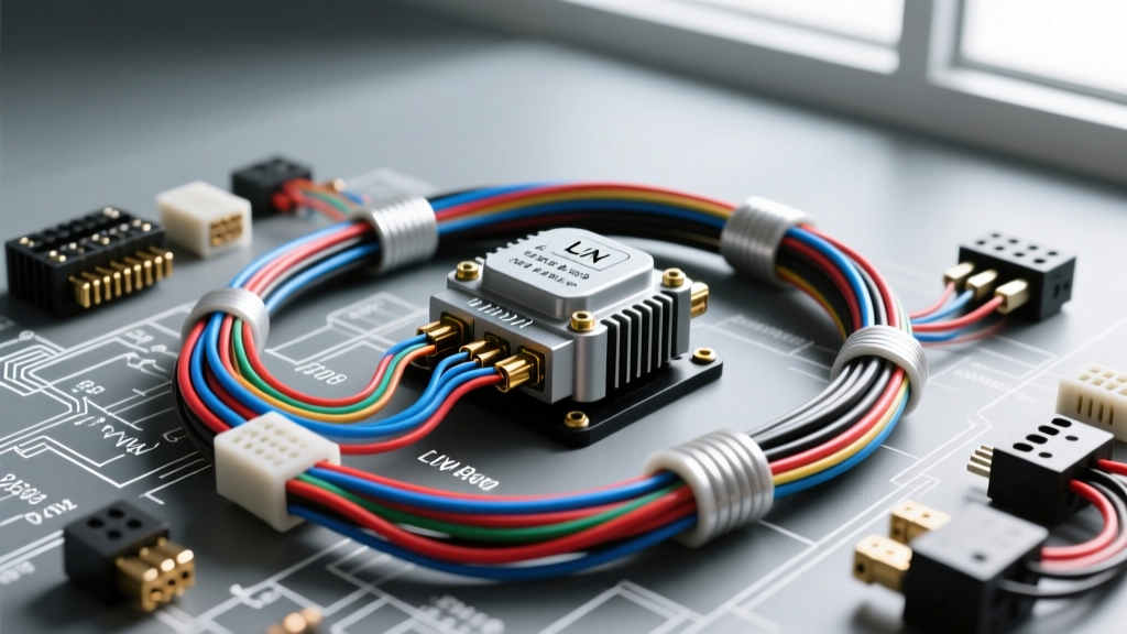
Introduction to ALTEST in Modern Auto Electric Systems
The term ALTEST (Alternator Test) in advanced auto electric diagnostics refers to the comprehensive evaluation of modern, computer-controlled charging systems. Gone are the days of simple analog voltage regulators relying on basic field and sense wires. Today's vehicles utilize sophisticated Local Interconnect Network (LIN) bus architectures to manage alternator output dynamically. This paradigm shift requires technicians to move beyond basic multimeter readings and embrace oscilloscope diagnostics, Pulse Width Modulation (PWM) analysis, and Battery Management System (BMS) integration protocols.
Performing a proper ALTEST auto electric procedure means understanding that the alternator is no longer an independent component; it is a slave module on a serial data network. The Powertrain Control Module (PCM) or dedicated Energy Management Module dictates the exact charging voltage based on battery state of charge (SOC), state of health (SOH), ambient temperature, and current electrical load. This advanced technical deep dive will dissect the wiring architecture, pin configurations, and diagnostic waveforms required to accurately troubleshoot LIN-controlled alternators found in modern European, Asian, and domestic vehicles.
The Shift from Analog to Digital: LIN Bus Alternator Architecture
Traditional alternators utilized a multi-terminal plug (typically IG, L, S, and F terminals) to monitor ignition voltage, lamp circuits, battery sense, and field duty cycles. While some of these analog designs persist in older or budget platforms, the industry standard has shifted to the LIN bus, as defined by SAE International J2621. The LIN bus is a single-wire, serial communication protocol that operates at a maximum baud rate of 20 kbps, making it highly resistant to electromagnetic interference (EMI) in the noisy under-hood environment.
In a LIN-controlled ALTEST scenario, the PCM acts as the master node, sending a 12V square-wave PWM signal to the alternator's internal regulator (the slave node). The alternator, in turn, modulates the field current to achieve the requested voltage and sends a feedback signal (often called the Duty Cycle Field Monitor or DFM) back to the PCM. If the LIN bus wire experiences high resistance, a short to ground, or an open circuit, the alternator defaults to a fail-safe mechanical voltage, usually between 13.5V and 13.8V, which can easily be misdiagnosed as a 'normal' charge by an inexperienced technician using only a basic digital multimeter (DMM).
Terminal Definitions and Wiring Harness Specifications
To execute a precise ALTEST auto electric diagnosis, you must identify the specific pinout of the alternator connector. Most modern Bosch, Denso, and Valeo LIN alternators utilize a 2-pin or 3-pin weather-sealed connector (often TE Connectivity AMPseal or equivalent). Below is a standardized reference chart for a typical 3-pin LIN alternator harness found in late-model VAG (Volkswagen/Audi Group) and Ford applications.
| Terminal ID | Function | Wire Gauge (AWG/mm²) | Typical Wire Color | Circuit Protection |
|---|---|---|---|---|
| B+ | Main Battery Output | 2 AWG / 35 mm² | Red (Heavy Cable) | 150A - 250A Mega Fuse |
| PIN 1 (LIN/COM) | PCM Command Signal | 20 AWG / 0.5 mm² | Green/White or Purple | Fused via PCM internal driver |
| PIN 2 (DFM/DF) | Field Monitor Feedback | 20 AWG / 0.5 mm² | Blue or Gray/White | Fused via PCM internal driver |
| PIN 3 (IG/15) | Ignition Wake-Up (Select) | 18 AWG / 0.75 mm² | Black/Red | 10A Mini Fuse in Cabin |
Note: The B+ terminal utilizes an M8 flange nut. According to Bosch Automotive Electrics specifications, the torque specification for the B+ terminal nut is strictly 12-15 Nm (8.8-11 lb-ft). Over-torquing can crack the internal rectifier bridge diode housing, leading to catastrophic internal shorts.
Executing the ALTEST Procedure: Oscilloscope and Multimeter Metrics
A true ALTEST auto electric deep dive requires capturing the communication waveforms. A DMM will only show an averaged DC voltage (typically 7V to 9V on the LIN line), which is useless for diagnosing communication dropouts or duty cycle faults. You must connect a digital storage oscilloscope (DSO) to the LIN command wire and the DFM feedback wire.
Step 1: Baseline Voltage, BMS Integration, and Ripple Testing
Before probing the data lines, verify the physical health of the charging circuit and the Intelligent Battery Sensor (IBS) located on the negative battery terminal. The IBS monitors battery temperature, voltage, and current flow, transmitting this data to the PCM via a separate LIN bus. If the IBS is faulty or the BMS was not reset after a battery replacement, the PCM will inhibit high-voltage charging to protect what it perceives as an aged battery.
- Static Voltage Test: Key-On, Engine-Off (KOEO). Measure voltage at the B+ terminal and compare it to the battery positive post. Any drop greater than 0.05V indicates corrosion at the mega fuse or the starter junction block.
- AC Ripple Test: Engine running at 2,000 RPM with high electrical load (headlights, HVAC blower on max). Set the DMM to AC Volts and probe the battery. A healthy alternator diode trio will produce less than 50mV (0.050V) AC. Readings above 100mV indicate a failed rectifier diode, requiring alternator replacement.
Step 2: PWM Duty Cycle Analysis on the LIN Command Line
Connect your oscilloscope ground to the engine block (verified clean ground) and the probe to the LIN command wire at the alternator connector (back-probe using a T-pin to maintain weather seal integrity). The PCM commands the alternator by varying the duty cycle of the 12V square wave. The following duty cycle parameters are standard across most OEM ALTEST auto electric diagnostic trees:
- 10% Duty Cycle: Default / Fault Mode. The PCM has lost communication with the alternator. The internal regulator defaults to a fixed 13.5V output to keep the vehicle running safely.
- 20% Duty Cycle: Freewheeling / Deceleration Fuel Cut-Off (DFCO). During vehicle deceleration, the PCM commands the alternator to stop charging, reducing parasitic drag on the engine and improving fuel economy. Voltage will drop to battery resting voltage (~12.6V).
- 50% Duty Cycle: Standard Maintenance Charge. Target voltage is typically 14.2V to 14.4V for standard flooded lead-acid batteries.
- 80% Duty Cycle: High Load / AGM Absorption Charge. Target voltage rises to 14.8V to 15.3V. This is commonly seen immediately after engine cranking or when the IBS detects a low State of Charge (SOC) in an Absorbent Glass Mat (AGM) battery.
- 90% Duty Cycle: Maximum Output / Diagnostic Mode. Often triggered during active ALTEST scan tool commands to verify maximum alternator amperage output.
Common Failure Modes and Harness Degradation
When the ALTEST auto electric procedure reveals an anomaly on the oscilloscope, the fault usually lies in one of three areas: the alternator internal regulator, the PCM driver, or the wiring harness. Because the LIN bus operates in a harsh environment, harness degradation is the most frequent culprit.
Voltage Drop Testing the LIN and Ground Circuits
Do not perform resistance checks on the LIN bus wire; the multimeter's low test voltage will not reveal high-resistance corrosion that affects a 12V PWM signal. Instead, perform a dynamic voltage drop test.
- Start the engine and turn on the rear defroster and headlights to force the PCM to command a high duty cycle (approx. 70-80%).
- Set your DMM to DC Volts.
- Place the red probe on the PCM LIN pin (at the PCM connector) and the black probe on the alternator LIN pin (back-probed).
- A healthy circuit will show a voltage drop of less than 0.1V. If the DMM reads 2.0V or higher, there is severe copper oxidation or a partial break in the 20 AWG wire, usually located within 6 inches of the alternator connector where heat and vibration are highest.
- Repeat the test for the alternator case ground. Place one probe on the alternator housing (bare metal) and the other on the negative battery post. A drop greater than 0.05V under load indicates a corroded engine-to-chassis ground strap, which will severely distort the LIN bus square wave and trigger false PCM codes for 'Generator Communication Bus' faults.
Advanced Diagnostic Summary
Mastering the ALTEST auto electric protocol requires a fundamental shift from component-level testing to network-level diagnostics. Modern alternators are precision instruments managed by complex energy algorithms. By utilizing an oscilloscope to verify PWM duty cycles, respecting the torque specifications of high-amperage B+ terminals, and understanding the symbiotic relationship between the IBS, the PCM, and the LIN bus, technicians can accurately diagnose charging system faults that defy traditional multimeter testing. For further diagnostic trees and OEM-specific wiring schematics, professionals should consult ALLDATA Diagnostic Procedures and manufacturer-specific technical service bulletins.