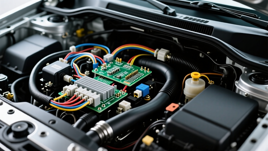
The Anatomy of a Botched Auto Electrical Job
When a vehicle arrives at a diagnostic bay with parasitic draws, erratic module behavior, or melted harnesses, the root cause is rarely a factory defect. More often than not, the culprit is an aftermarket modification or a poorly executed repair. A professional car electrical engineer approaches vehicle architecture not just as a collection of wires, but as a highly sensitive network of multiplexed data and high-current inductive loads.
Ignoring the fundamental laws of electricity in a modern vehicle doesn't just cause a blown fuse; it can destroy a $1,500 Powertrain Control Module (PCM) or induce a thermal event. Below are the most critical wiring mistakes and safety warnings that separate professional engineering standards from dangerous DIY guesswork.
Mistake #1: Piercing CAN Bus Networks with Scotch-Loks
The most catastrophic mistake seen in modern automotive diagnostics is tapping into Controller Area Network (CAN) lines using insulation-displacement connectors (commonly known as Scotch-Loks).
The Engineering Reality of Multiplexing
High-speed CAN (ISO 11898-2) operates using a differential signaling method across a twisted pair of wires: CAN-High and CAN-Low. The twist rate is engineered to cancel out electromagnetic interference (EMI), and the network relies on a strict 120-ohm terminating resistance at each end of the bus.
- The Mistake: Clamping a Scotch-Lok onto a CAN wire crushes the dielectric insulation, alters the physical geometry of the twisted pair, and introduces parasitic capacitance.
- The Result: Signal reflection, impedance mismatch, and complete network dropout. This causes the dashboard to light up like a Christmas tree, transmission limp-mode, and no-start conditions.
- The Fix: Never pierce data lines. If a breakout is absolutely necessary, an engineer will cut the wire, solder a proper Y-harness using MIL-SPEC solder sleeves (e.g., Raychem SolderSleeve), and maintain the twist rate up to the breakout point.
Mistake #2: Sizing Wire by Amperage, Ignoring Voltage Drop
Amateur wire guides often suggest using 10 AWG wire for a 30-Amp circuit. While a 10 AWG copper wire might not melt at 30 Amps, a car electrical engineer knows that thermal limits are only half the equation. Voltage drop over distance is the silent killer of automotive electronics.
Voltage Drop Calculation Table: Starter & Fuel Pump Circuits
Fuel pumps and starter solenoids are highly sensitive to voltage starvation. A drop of just 1.5 volts at the fuel pump can result in a 30% loss in fuel volume delivery.
| Circuit Type | Continuous Load | Wire Length (Pos + Neg) | Minimum AWG (Chassis Ground) | Dedicated Ground AWG | Max Allowable Drop |
|---|---|---|---|---|---|
| EFI Fuel Pump (In-Tank) | 15A - 22A | 16 ft | 10 AWG | 10 AWG | < 0.5V (Under Load) |
| Starter Motor Solenoid | 40A (Inrush) | 12 ft | 8 AWG | N/A (Block Ground) | < 0.2V (Cranking) |
| Starter Motor Main Feed | 250A+ (Cranking) | 14 ft | 1/0 AWG | 1/0 AWG (Engine to Chassis) | < 0.5V Total System |
| HID/LED Headlight Ballast | 8A (Inrush 15A) | 10 ft | 14 AWG | 14 AWG (Direct to Battery) | < 0.3V |
Note: Modern vehicles use a "floating ground" or chassis-return system. Upgrading the positive feed to 8 AWG while leaving a corroded 14 AWG factory ground path will yield zero performance gains. Both positive and negative paths must be upgraded simultaneously.
Mistake #3: The "Daisy Chain" Ground Loop
Audio installers and amateur fabricators frequently daisy-chain multiple high-current accessories (amplifiers, fuel cells, cooling fans) to a single 1/0 AWG ground cable bolted to a seatbelt anchor.
Why Engineers Hate Ground Loops
When multiple high-current devices share a single ground path, the resistance of the shared wire creates a fluctuating voltage potential between the devices. If an amplifier and an ECU share a ground path, the massive current draw from the amplifier's bass transients modulates the ground reference for the ECU's analog sensors (like the MAF or O2 sensors). This introduces "noise" into the sensor data, causing erratic fuel trims and misfires. Always run dedicated ground wires for high-current modules directly to bare, unpainted chassis metal or the negative battery terminal.
Mistake #4: Using Standard Relays for Inductive Loads Without Suppression
Electric cooling fans, AC compressors, and fuel pumps are inductive loads. When the magnetic field in an inductive coil collapses (when the relay opens), it generates a massive reverse-voltage spike—often exceeding 100 volts for a fraction of a millisecond.
- The Danger: If this spike travels back into a solid-state control module (like a PWM fan controller or a PCM driver), it will instantly fry the internal logic board.
- The Engineering Standard: A car electrical engineer specifies relays with built-in suppression diodes or resistors for PCM-controlled circuits. If using a standard Bosch-style 30/87 relay, a flyback diode (e.g., 1N5408) must be soldered in reverse bias across terminals 85 and 86 to safely route the inductive spike back into the coil.
Mistake #5: Tapping into the Alternator 'L' or 'S' Terminals for Accessories
It is a common, albeit dangerous, forum myth that the Alternator's 'L' (Lamp/Exciter) or 'S' (Sense) terminals can be used as a switched 12V source to trigger aftermarket relays.
The 'L' terminal on many modern internally regulated alternators (such as the GM CS130D or Denyo units) is connected directly to the PCM's solid-state driver. Pulling even 50 milliamps of extra current to fire a relay coil through this circuit will overload the PCM's internal transistor, resulting in a fried computer and a dead battery. Always use a dedicated ignition-switched source fused at 5A to trigger aftermarket relay coils.
Mistake #6: Ignoring Thermal Derating in Engine Bays
Wire ampacity charts are typically based on an ambient temperature of 30°C (86°F). Under-hood temperatures near exhaust manifolds or turbochargers routinely exceed 120°C (248°F). At these temperatures, the current-carrying capacity (ampacity) of copper wire drops by up to 40%. Using standard PVC-jacketed wire (like GXL) near heat sources will result in the insulation melting and shorting against the engine block. Engineers mandate the use of cross-linked polyethylene (TXL) or Tefzel wire, wrapped in fiberglass or titanium heat-sleeving, for any routing within 12 inches of exhaust components.
Mistake #7: The Missing Mega-Fuse on High-Amp Feeds
Running a 1/0 AWG battery cable to a rear-mounted distribution block or inverter without a main overcurrent protection device is a severe fire hazard. A 1/0 AWG wire can easily sustain 300+ Amps indefinitely. If that wire chafes against a sharp metal edge, the battery will dump its entire cold-cranking amp (CCA) rating (often 800+ Amps) into the short circuit, instantly welding the wire to the chassis and igniting the vehicle.
Safety Rule: An ANL or Class-T Mega-Fuse, rated appropriately for the wire size and load (e.g., 250A for a standard aftermarket audio/system feed), must be installed within 18 inches of the positive battery terminal.
Authoritative Diagnostic & Repair Standards
To ensure safety and reliability, auto electrical repairs must adhere to established industry protocols. For deeper technical reference on OEM wiring standards and safety protocols, consult the following resources:
- SAE J1128 (Low Tension Primary Cable Standard): The definitive Society of Automotive Engineers standard for wire insulation types, thermal ratings, and AWG specifications in automotive applications.
- Del City Wire - Automotive Wiring & Circuit Protection Guides: Comprehensive derating charts, voltage drop calculators, and terminal crimp specifications trusted by marine and automotive electrical engineers.
- NHTSA Guidelines on Vehicle Modifications: Federal safety warnings regarding the alteration of factory electrical harnesses, airbag circuits (SRS), and CAN bus safety systems.