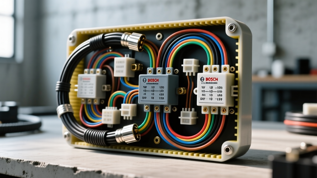
Introduction to the Louis Auto Electrical Method
When approaching automotive wiring for the first time, the sheer volume of connectors, wire gauges, and circuit diagrams can be overwhelming. The "Louis Auto Electrical" methodology is a foundational teaching framework used by master technicians to simplify 12V DC systems into digestible, fail-safe concepts. Unlike household AC wiring, automotive electrical systems operate in a harsh environment characterized by extreme temperature fluctuations, high vibration, and exposure to corrosive road chemicals. This guide will walk you through the beginner-friendly fundamentals of auto electrical work, ensuring your first custom harness or accessory installation is both safe and reliable.
Core Principle 1: Selecting the Right Wire (SAE Standards)
The most common mistake beginners make is using household solid-core wire or standard PVC-insulated wire in a vehicle. The Louis Auto Electrical standard strictly mandates the use of stranded copper wire with cross-linked polyethylene insulation, specifically GXL, TXL, or SXL grades. These insulation types are designed to withstand under-hood temperatures up to 125°C (257°F) and resist melting against hot exhaust components. According to the SAE J1128 standard, automotive wire must also feature a specific strand count to handle high-frequency vibrations without suffering from metal fatigue and internal breakage.
AWG Sizing and Ampacity Chart
Wire gauge is measured in American Wire Gauge (AWG). The lower the number, the thicker the wire and the higher the current it can safely carry. Always size your wire based on the maximum continuous draw of the circuit, not just the peak draw. Below is a reference chart for standard 12V DC automotive applications:
| AWG Size | Max Amps (Chassis Wiring) | Typical Application | Recommended Fuse Size |
|---|---|---|---|
| 18 AWG | 6A - 8A | LED lighting, ECU sensor signals, relays coils | 5A - 7.5A |
| 16 AWG | 10A - 12A | Interior lighting, horn, wiper motors | 10A |
| 14 AWG | 15A - 18A | Fuel pumps, power windows, cigarette lighter sockets | 15A |
| 12 AWG | 20A - 25A | High-power audio amplifiers, cooling fans, aftermarket seats | 20A |
| 10 AWG | 30A - 40A | Starter solenoids, main accessory feeds, winches | 30A |
| 8 AWG | 45A - 55A | Alternator output upgrades, main battery cables | 50A |
Core Principle 2: Circuit Protection and Fusing
A wire is only as safe as the fuse protecting it. The primary purpose of a fuse is to protect the wire from catching fire, not necessarily the component it powers. The Louis Auto Electrical rule of thumb for fusing is to select a fuse rated at no more than 80% of the wire's maximum ampacity. For example, if you are running a 14 AWG wire capable of handling 18 amps, you should use a 15A ATO/ATC blade fuse. As detailed in the Littelfuse Automotive Fuse Guide, standard blade fuses (ATO/ATC) are ideal for general cabin and engine bay circuits, while Maxi fuses should be reserved for high-amperage main feeds, and Mini/LOWPROFILE MINI fuses are best for modern, high-density OEM fuse boxes.
Core Principle 3: Mastering the Bosch-Style Relay
Beginners often attempt to run high-draw accessories like off-road light bars or radiator fans directly through a dashboard toggle switch. This results in melted switches and severe voltage drop. A relay allows a low-current switch to control a high-current circuit safely. The industry-standard Bosch-style ISO mini relay features either 4 or 5 pins, universally numbered according to DIN 72552 standards.
Relay Pinout Breakdown
- Pin 30 (Common): High-current power input directly from the battery (via a fuse).
- Pin 85 (Coil Ground): Ground connection for the internal electromagnet coil.
- Pin 86 (Coil Power): Switched 12V+ input from your dashboard switch or ECU trigger.
- Pin 87 (Normally Open - NO): High-current output to the accessory. Power only flows here when the relay is energized.
- Pin 87a (Normally Closed - NC): (5-pin relays only) High-current output that receives power when the relay is OFF. Used for dual-circuit switching, such as switching between high and low beam headlights.
Pro Tip: When wiring a standard 4-pin relay for an accessory, always place the main fuse on the Pin 30 power feed, as close to the battery positive terminal as physically possible (within 7 inches is the SAE recommendation).
Core Principle 4: Connectors and Terminations
Twist-and-tape splices have no place in a reliable automotive harness. The Louis Auto Electrical methodology emphasizes the use of environmentally sealed connectors for any circuit exposed to the elements. The two most common connector families you will encounter are:
- Weather-Pack Connectors: Originally developed by Delphi (now Aptiv), these feature large, cylindrical silicone seals that provide excellent water and dust resistance. They are ideal for engine bay sensors, exterior lighting, and bulkhead pass-throughs. They require specific open-barrel crimping dies and a dedicated insertion tool to seat the pins past the retaining tangs.
- Deutsch DT Series: The gold standard for high-vibration, heavy-duty applications (common in agriculture, marine, and off-road lighting). They utilize solid cylindrical pins and sockets with a secondary green or orange wedge lock to prevent the pins from backing out under extreme vibration.
For interior, cabin-side connections, standard Metri-Pack 150 or 250 series connectors offer a compact footprint while still providing basic moisture resistance via individual wire seals.
Core Principle 5: Voltage Drop Testing
A multimeter is an auto electrician's best friend, but beginners often misuse it by only testing for continuity or simple battery voltage. The most powerful diagnostic tool in your arsenal is the Voltage Drop Test. A circuit may show 12.6V at the battery, but if there is high resistance (corrosion, loose crimp, or undersized wire) in the harness, the accessory might only receive 9V under load, causing it to malfunction or overheat the wire.
Step-by-Step Voltage Drop Testing
- Set your multimeter to DC Volts (20V range).
- Turn the circuit ON so current is actively flowing through the wire.
- Place the red multimeter probe on the positive battery terminal.
- Place the black multimeter probe on the positive terminal of the accessory (e.g., the input side of a fuel pump).
- Read the display. A healthy positive-side circuit should show a voltage drop of less than 0.2V. If you read 1.5V, you have found a high-resistance fault between the battery and the component.
- Repeat the test for the ground side: place the red probe on the negative terminal of the accessory and the black probe on the negative battery post. The ground-side voltage drop should also be less than 0.2V.
Summary and Best Practices
Adopting the Louis Auto Electrical fundamentals will immediately elevate the quality and safety of your automotive projects. Always use GXL/TXL stranded wire, protect every circuit with a properly sized ATO or MAXI fuse, utilize Bosch-style relays to isolate high-current loads from delicate dashboard switches, and terminate your wires with ratcheting open-barrel crimp tools and sealed connectors. Finally, verify your work with a voltage drop test rather than relying solely on visual inspections or simple continuity checks. By respecting the unique demands of the 12V DC automotive environment, you will build harnesses that last the lifetime of the vehicle.