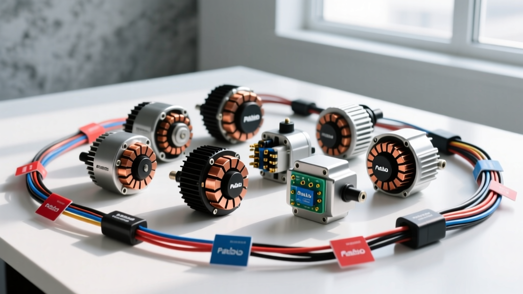
Introduction to Pablo Auto Electrical Component Tiers
When upgrading a vehicle electrical architecture for high-draw accessories, off-road winching, or competitive car audio, selecting the right charging component is critical. Pablo Auto Electrical has emerged as a prominent manufacturer in the aftermarket space, offering alternators that bridge the gap between standard OEM replacements and ultra-high-output racing units. However, simply bolting on a high-amp unit without understanding the underlying stator technology, voltage regulator pinouts, and necessary charge wire upgrades will result in voltage drop, melted harnesses, or ECU damage. This guide breaks down the Pablo Auto Electrical product lineup, comparing their OEM-Plus and Pro-Series tiers, and provides actionable wiring specifications for a flawless installation.
Pablo OEM-Plus vs. Pro-Series High-Output: Core Differences
Pablo Auto Electrical categorizes their alternators into two primary tiers. The OEM-Plus line is designed as a direct drop-in replacement for daily drivers requiring slightly more headroom for auxiliary lighting or mild audio upgrades. The Pro-Series is engineered for extreme continuous loads, utilizing advanced thermal management and transient voltage suppression.
| Specification | Pablo OEM-Plus (140A-160A) | Pablo Pro-Series (220A-300A) |
|---|---|---|
| Stator Design | Standard Round-Wire | Hairpin (Flat-Wire) Stator |
| Copper Slot Fill | ~45% | ~70% |
| Rectifier Diodes | Standard Silicon (6-Diode) | Zener-Clamped TVS (8-Diode) |
| Bearings | Standard Sealed (6202/6303) | High-Temp SKF/NTN (C3 Clearance) |
| Idle Output (at 800 RPM) | 90A - 110A | 160A - 200A |
| Pulley Type | Solid V-Ribbed | Overrunning Alternator Pulley (OAP) |
The Hairpin Stator Advantage
The most significant differentiator in the Pablo Pro-Series is the hairpin stator. Traditional round-wire stators leave significant empty space in the stator slots, limiting the amount of copper that can generate the magnetic field. By using rectangular flat-wire conductors, Pablo achieves a 70% slot fill ratio. This drastically reduces internal resistance (I²R losses), allowing the alternator to produce higher amperage at lower RPMs while running significantly cooler under sustained 200A+ loads.
Voltage Regulator Pinouts and Wiring Architecture
Many Pablo Auto Electrical high-output units utilize the widely adapted GM CS130/CS144 style 4-pin internal regulator architecture due to its reliability and ease of integration into custom harnesses. Miswiring the excitation and sense circuits is the leading cause of premature regulator failure.
- Pin L (Lamp/Excitation): Requires an 18 AWG wire (typically Purple/White). This circuit provides the initial excitation current to turn the alternator on. It must be routed through a 194 bulb or a 500-ohm resistor to ground to prevent voltage spikes if the bulb blows.
- Pin I (Ignition): 18 AWG (Pink). Connects to a switched 12V source. This wakes the regulator and prevents battery drain when the engine is off.
- Pin F (Field): Used for PCM monitoring via PWM signaling. If running standalone, this pin is left unconnected or tied to a diagnostic LED.
- Pin S (Sense): Critical Circuit. Requires a 12 AWG wire (Red). This wire tells the regulator what voltage is actually reaching the battery. It MUST be routed directly to the positive battery post or the main distribution block. If you route the Sense wire to the alternator output post, the regulator will read artificially high voltage due to charge wire voltage drop, resulting in severe battery undercharging.
For deeper integration into modern CAN-bus systems, Pablo provides an optional external LIN-bus adapter module that translates the Pro-Series internal PWM signals into digital commands readable by factory Body Control Modules (BCMs), preventing dash cluster battery warning lights.
Upgrading the Charge Wire and Grounding
Installing a 250A Pablo Pro-Series alternator on a factory 8 AWG charge wire is a fire hazard. Factory 8 AWG wire is generally rated for 40A-50A continuous in an under-hood environment. Pushing 200A through it will cause massive voltage drop, melting the insulation and potentially shorting against the exhaust manifold.
Charge Wire Sizing Chart
| Alternator Output | Minimum Wire Gauge (SGX) | Recommended Fuse (Class T) |
|---|---|---|
| 140A - 160A | 4 AWG | 175A |
| 180A - 220A | 1/0 AWG | 250A |
| 240A - 300A | 2/0 AWG | 350A |
Termination Best Practices: When terminating 1/0 AWG or 2/0 AWG SGX welding cable, do not use solder. Solder creates a brittle joint that will crack under engine vibration. Use a 12-ton hydraulic hex-crimper with oxygen-free copper ring terminals. Seal the termination with dual-wall, adhesive-lined marine heat shrink to prevent copper oxidation and acid creep.
The Forgotten Ground Strap
An alternator can only output what the ground path can return to the battery. Factory braided ground straps often corrode or are undersized for high-amp builds. Upgrade the engine block-to-chassis ground using a minimum 2 AWG flexible copper strap. When securing the ground to the engine block, use an M10x1.5 bolt with a star lock washer to bite through paint and powder coating. Torque the M10 ground bolt to exactly 35 lb-ft to ensure optimal surface contact without stripping the aluminum block threads.
Overrunning Alternator Pulleys (OAP) and Belt Harmonics
The Pablo Pro-Series features an Overrunning Alternator Pulley (OAP), commonly known as a decoupler pulley. Modern engines with aggressive cylinder deactivation or high-compression diesels create massive torsional vibrations in the serpentine belt drive. A solid pulley transfers these spikes directly to the alternator bearings and the belt tensioner, causing belt slip and bearing brinelling. The OAP contains an internal one-way clutch and torsion spring that absorbs these spikes, allowing the alternator rotor to coast momentarily during engine deceleration. Note: Never use standard impact guns to remove an OAP; you must use a specialized splined OAP holding tool and a 17mm hex socket to prevent destroying the internal clutch mechanism.
Real-World Failure Modes and DSO Diagnostics
Even premium units can suffer from installation-induced failures. When troubleshooting a Pablo Auto Electrical alternator, skip the basic multimeter and use a Digital Storage Oscilloscope (DSO) to check for AC Ripple.
- Symptom: Battery voltage fluctuates between 12.8V and 14.8V at idle; headlights pulse.
- DSO Test: Connect the DSO positive lead to the battery positive post and the negative lead to the battery negative post. Set the DSO to AC coupling, 100mV/div, and 5ms/div.
- Analysis: A healthy Pablo rectifier bridge will show a flat line or a very tight ripple of <30mV AC. If you see a jagged waveform exceeding 100mV AC, or a missing 'hump' in the 3-phase pattern, one or more diodes in the rectifier assembly have shorted or opened.
- Root Cause: Diode burnout is almost always caused by 'Load Dump'—disconnecting the battery while the engine is running, or a poor ground causing the regulator to over-field the stator in a desperate attempt to reach target voltage.
By understanding the architectural differences between the OEM-Plus and Pro-Series lines, correctly wiring the CS-style regulator sense circuits, and scaling your charge wire AWG to match the output, your Pablo Auto Electrical upgrade will provide years of bullet-free, high-amperage charging. For further reading on standard wiring practices, refer to the MAD Electrical Alternator Tech Guide and the SAE J1171 Ignition Protection Standard for marine and high-vibration alternator safety requirements.