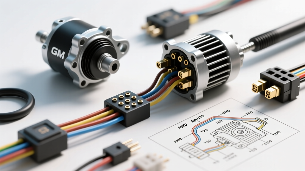
Demystifying Core Car Electrical Parts
When you pop the hood of a vehicle, the sheer volume of wiring, sensors, and modules can be overwhelming. However, understanding car electrical parts does not require an engineering degree. At the heart of every traditional internal combustion vehicle lies a foundational 12-volt architecture centered around two massive power players: the alternator and the starter motor. For beginners and DIY enthusiasts, mastering the wiring, pinouts, and power delivery of these two components is the ultimate gateway to automotive electrical confidence.
In this guide, we will break down the fundamentals of General Motors (GM) 12V charging and cranking systems—specifically focusing on the ubiquitous Delco Remy CS130D alternator and the PG260D gear-reduction starter. We will cover exact wire gauges, terminal pinouts, crimping standards, and real-world troubleshooting strategies to ensure your vehicle's electrical heartbeat remains strong.
The Alternator: Heart of the Charging System
The alternator is responsible for replenishing the battery and powering the vehicle's electrical loads while the engine runs. The GM CS130D (common in 1990s through early 2000s GM trucks and sedans) is a prime example of a modern, internally regulated, computer-controlled alternator. Unlike older 1-wire setups, the CS130D utilizes a 4-pin connector to communicate with the Powertrain Control Module (PCM) and monitor system voltage.
CS130D 4-Pin Connector Pinout & Wire Colors
To properly wire or diagnose a CS130D, you must understand the function of each cavity in the pigtail connector. Using the incorrect wire gauge or misrouting the 'Sense' wire is a leading cause of undercharging and dim headlights.
| Pin | Function | Typical Wire Color | AWG Size | Routing / Notes |
|---|---|---|---|---|
| P | PCM Control | Gray | 18 AWG | PWM signal from PCM to command alternator output. |
| F | Field Duty Cycle | Red/White | 18 AWG | Feedback signal to PCM indicating alternator load. |
| L | Lamp / Ignition | Brown/White | 16 AWG | 12V+ from ignition switch; turns on the dash 'BAT' light. |
| S | Voltage Sense | Red | 14 AWG | Must route directly to the battery positive or main fuse block. |
Expert Insight: The 'S' (Sense) pin is critical. If this wire is broken, or if it is jumpered directly to the alternator's BAT terminal (a common DIY mistake), the alternator will sense voltage at its own case rather than at the battery. Because of voltage drop across the engine bay wiring, the battery will chronically undercharge, leading to sulfation and premature failure. Always run a dedicated 14 AWG fused sense wire to the battery positive.
Main Output Wiring & Fusing
The large threaded stud on the back of the alternator is the BAT (Battery) terminal. A stock CS130D typically produces between 105A and 140A. According to SAE J1113 standards and standard automotive wiring charts, a 105A alternator requires a minimum of 4 AWG copper wire for runs under 5 feet. If you upgrade to a high-output 200A+ alternator for off-road lighting or heavy audio systems, you must step up to 1/0 AWG welding cable. Furthermore, this main power wire must be protected by an ANL or Mega fuse rated at roughly 125% of the alternator's maximum output (e.g., a 150A fuse for a 120A alternator), mounted within 7 inches of the battery positive terminal.
The Starter Motor: Cranking Circuit Basics
While the alternator sustains the electrical system, the starter motor initiates it. Cranking an engine requires a massive, instantaneous surge of amperage—often exceeding 400 amps. The GM Delco Remy PG260D is a permanent magnet gear reduction (PMGR) starter widely used across GM V8 platforms. It features two primary electrical connection points on the solenoid.
Solenoid Terminals & Power Delivery
- BAT Terminal (Large Stud): This is the direct power feed from the battery. Because of the extreme amperage draw (400A-600A peak), this circuit demands 2/0 AWG pure copper battery cable. Any undersized wiring here will result in severe voltage drop, causing the starter to spin sluggishly and generating enough heat to melt the insulation.
- S Terminal (Small Blade/Spade): This is the trigger wire. When you turn the key to 'START', a 12V signal is sent to this terminal to engage the solenoid plunger. This wire is typically 12 AWG Purple.
- R Terminal (Optional Bypass): Historically used to send a 12V bypass signal to the ignition coil during cranking (bypassing the ballast resistor). On modern HEI (High Energy Ignition) systems, this terminal is usually left empty.
Upgrading to a Starter Relay
Relying on the factory ignition switch to carry the 15-20 amps required to pull in a heavy-duty starter solenoid is a recipe for burnt ignition switches and voltage drop. A fundamental upgrade for any car electrical parts enthusiast is installing a Bosch-style 5-pin 40A relay near the starter. Here is the standard wiring pinout for the relay:
| Relay Pin | Function | Wire Gauge & Color | Connection Point |
|---|---|---|---|
| 30 | Constant 12V Power | 10 AWG Red | Fused direct from Battery Positive |
| 87 | Switched Output | 12 AWG Purple | Starter Solenoid 'S' Terminal |
| 86 | Ignition Trigger | 14 AWG Pink | Factory 'START' trigger wire |
| 85 | Relay Ground | 14 AWG Black | Clean engine block ground point |
| 87a | Normally Closed | N/A | Not used in this application |
By routing the heavy current through the relay, the factory ignition switch only handles the tiny milliamp load of the relay coil, vastly extending its lifespan and ensuring maximum voltage reaches the starter solenoid.
Grounding: The Forgotten Car Electrical Part
Beginners often obsess over the positive power wires but completely neglect the ground side of the circuit. Electricity must return to the source. A poor ground will mimic a failing alternator or a dead starter. The Haynes Automotive Electrical Manual emphasizes that voltage drop testing on the ground side is the most accurate way to diagnose cranking issues.
Essential Grounding Points & Specs
- Battery to Engine Block: Must be 1/0 AWG or 2/0 AWG flexible braided copper. This carries the full 500A return load during cranking.
- Engine Block to Chassis: 4 AWG strap. Ensures the engine bay accessories (alternator case, AC compressor clutch) have a clean return path.
- Battery to Chassis: 2 AWG wire. Grounds the vehicle's body for lighting, PCM, and interior electronics.
Torque Specifications: Ground connections are only as good as the metal-to-metal contact. Always use a wire brush to remove paint, rust, and corrosion down to bare, shiny metal. Apply a thin coat of dielectric grease *over* the connection after tightening to prevent oxidation. GM side-terminal battery posts should be torqued to exactly 12-15 ft-lbs; overtightening will strip the soft lead threads inside the battery.
Wiring Standards & Crimping Methodology
When replacing or upgrading car electrical parts, the method of termination is just as critical as the wire gauge. Never use solder on high-vibration, high-amperage automotive connections like starter lugs or alternator rings. Solder can become brittle and crack under engine harmonic vibration, leading to arcing and fires.
Instead, use a heavy-duty hex-crimp tool for closed-end ring terminals. After crimping, seal the connection using adhesive-lined polyolefin heat shrink. When heated, the inner lining melts and flows into the wire strands, creating a waterproof, oxygen-free seal that prevents green copper corrosion (verdigris) from creeping up inside the insulation.
Beginner Troubleshooting Decision Tree
When your vehicle exhibits electrical gremlins, use this structured approach to isolate the faulty car electrical part. You will need a digital multimeter (DMM) set to DC Volts.
Symptom 1: Engine Cranks Very Slowly
- Step 1: Check battery resting voltage. (Must be 12.6V). If below 12.2V, charge and load-test the battery.
- Step 2: Perform a Voltage Drop Test on the positive side. Place the red probe on the battery post and the black probe on the starter BAT stud while an assistant cranks the engine. A reading over 0.5V indicates high resistance in the positive cable or connections.
- Step 3: Perform a Voltage Drop Test on the ground side. Place the red probe on the starter case (bare metal) and the black probe on the battery negative post while cranking. A reading over 0.2V means your engine block ground is corroded or undersized.
Symptom 2: Headlights Dim at Idle, Brighten When Revving
- Step 1: Measure voltage at the battery with the engine running at 1500 RPM. It should read between 13.8V and 14.4V.
- Step 2: If battery voltage is low, measure voltage at the alternator BAT stud. If the alternator stud reads 14.2V but the battery reads 13.1V, you have excessive voltage drop on the main charging wire (upgrade from 4 AWG to 2 AWG).
- Step 3: Check the 'S' (Sense) wire on the alternator pigtail. Ensure it has a clean, unbroken path back to the battery positive.
Symptom 3: Dash 'BAT' Light Illuminates While Driving
- Step 1: The 'L' pin circuit is detecting a voltage mismatch. Check the Brown/White wire for chafing against the exhaust manifold or engine block.
- Step 2: If the wiring is intact, the internal voltage regulator or the diode trio inside the alternator has likely failed. The CS130D requires a full rebuild or replacement.
By understanding the specific pinouts, AWG requirements, and physical routing of these core car electrical parts, you transition from simply swapping components to truly engineering a reliable automotive electrical system. Always consult factory service manuals for vehicle-specific torque specs and routing diagrams before cutting or crimping any wires.