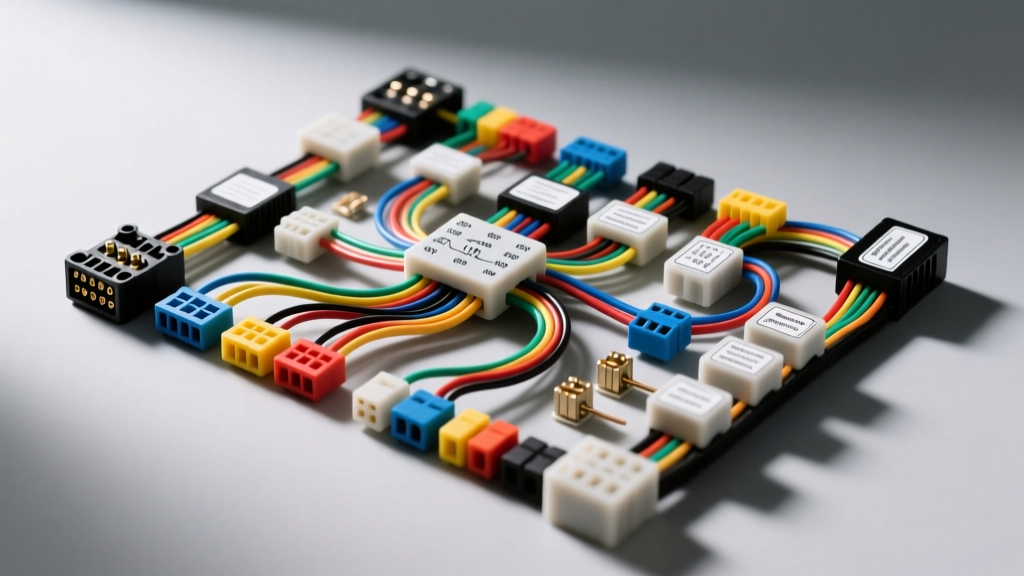
Introduction to Automotive Electrical Fundamentals
The modern vehicle is a rolling network of computers, sensors, and high-current actuators. For beginners, opening a fuse box or tracing a wiring harness can feel overwhelming. However, by breaking down the system into core principles, anyone can learn to diagnose and repair automotive circuits. When studying the diagnostic workflows of top midwestern shops, such as those setting the benchmark for Ankeny auto electric repairs, beginners quickly learn that mastering the basics—voltage, current, resistance, and circuit integrity—is far more valuable than memorizing complex wiring diagrams. Shops in regions like Ankeny, Iowa, deal with extreme temperature swings and heavy road salt usage, meaning their technicians must be experts in identifying corrosion, voltage drop, and insulation failure. This guide will walk you through the foundational concepts of automotive electrical systems, providing actionable, technical data you can apply to your own garage diagnostics.
The Four Pillars of a Complete Circuit
Every functional automotive circuit, whether it powers a simple dome light or a complex fuel injector, requires four fundamental components:
- Power Source: Typically the 12V battery or the alternator (which outputs 13.5V to 14.8V when the engine is running).
- Protection Device: A fuse or circuit breaker designed to melt or trip before the wiring harness catches fire. Fuses are rated by amperage (e.g., 10A, 15A, 20A) and speed (Mini, ATO, Maxi).
- Control Device: A switch, relay, or transistor (inside an ECU) that dictates when the circuit is active.
- Load: The component doing the actual work, such as a halogen bulb, electric motor, or solenoid. The load introduces resistance into the circuit, converting electrical energy into light, heat, or motion.
- Ground Path: The return path to the battery's negative terminal. In modern unibody vehicles, the steel chassis serves as the primary ground return to save weight and copper.
If any one of these pillars is compromised, the circuit fails. A common beginner mistake is assuming a dead component is the fault, when in reality, a corroded ground pillar is starving the load of amperage.
Wire Gauge (AWG) and SAE Insulation Standards
Selecting the correct wire gauge is critical. The American Wire Gauge (AWG) system dictates that a smaller number equals a thicker wire capable of carrying more current. Using wire that is too thin for a specific load will result in excessive resistance, severe voltage drop, and potentially a melted harness or electrical fire.
Standard Automotive AWG Sizing Chart
| AWG Size | Typical Application | Max Amperage (Chassis) |
|---|---|---|
| 18 AWG | ECU Sensors, CAN-bus lines, LED markers | 5A - 8A |
| 16 AWG | Headlights, tail lights, radio memory | 10A - 13A |
| 14 AWG | High-draw lighting, horn, power mirrors | 15A - 18A |
| 12 AWG | Power seats, power windows, cigarette lighter | 20A - 25A |
| 10 AWG | ABS modules, high-amperage cooling fans | 30A - 40A |
| 8 AWG | Alternator main output, amplifier power | 50A - 70A |
| 4 AWG | Starter motor, main battery ground | 120A - 150A |
Beyond gauge, insulation type matters. According to SAE International standards, most modern vehicles use GXL (General Cross-Linked) or TXL (Thin-wall Cross-Linked) insulation. TXL is preferred in tight engine bays because its thinner wall reduces harness bulk and weight while maintaining high-temperature resistance up to 125°C.
Decoding the ISO Mini Relay
Relays allow a low-current switch (like your headlight stalk) to control a high-current load (like 55W halogen headlights) without melting the switch contacts. The most common relay in automotive history is the Bosch-style ISO mini relay. Understanding its pinout is mandatory for any aspiring auto electrician.
| Pin Number | Function | Technical Details |
|---|---|---|
| 30 | Common / Power In | Receives constant 12V+ from the battery via a high-amperage fuse. |
| 85 | Coil Ground | Connects to chassis ground or an ECU-controlled ground driver. |
| 86 | Coil Power | Receives switched 12V+ from the dashboard switch or ignition. |
| 87 | Normally Open (NO) | Output to the load. Connects to Pin 30 only when the coil is energized. |
| 87a | Normally Closed (NC) | Connects to Pin 30 when the relay is OFF. Rarely used in standard OEM auto wiring. |
Diagnostic Tip: You can test a relay's internal electromagnetic coil using a digital multimeter (DMM). Set the DMM to Ohms (Ω) and probe pins 85 and 86. A healthy coil will typically read between 70 and 90 ohms. If the meter reads 'OL' (Open Loop), the internal wire is broken. If it reads near 0.0 ohms, the coil is shorted internally.
The Midwest Factor: Galvanic Corrosion and Grounds
Technicians working in areas with harsh winters, a reality for any Ankeny auto electric specialist, know that the enemy of electrical systems is galvanic corrosion. When copper wire terminals are bolted to an aluminum engine block or a painted steel chassis, and then exposed to moisture and magnesium chloride road salts, a galvanic battery effect occurs. This creates a crusty, non-conductive layer of oxidation that acts as a resistor.
To combat this, always use a wire brush to clean ground points down to bare, shiny metal before reattaching a ground strap. After securing the bolt to the manufacturer's torque specification, coat the entire connection in a silicone-based dielectric grease. Do not use petroleum-based greases, which can degrade rubber wire seals and certain plastic connectors over time.
Mastering the Voltage Drop Test
The hallmark of a professional automotive electrician is the voltage drop test. Unlike a continuity test, which requires the circuit to be dead and disconnected, a voltage drop test is performed on a live, active circuit under load. It measures exactly how much voltage is being 'lost' or consumed by unwanted resistance in the wires and connectors.
Step-by-Step Voltage Drop Procedure
- Turn the circuit ON so current is flowing (e.g., turn on the headlights or crank the starter).
- Set your DMM to DC Volts (VDC).
- Place the red multimeter probe on the battery positive terminal and the black probe on the load's positive terminal. Read the display.
- Next, place the red probe on the load's negative terminal and the black probe on the battery negative terminal. Read the display.
Maximum Allowable Voltage Drop Limits
- High-Current Circuits (Starter, Alternator, Main Grounds): Maximum 0.20V drop per side.
- Low-Current Circuits (Sensors, ECU, Lighting): Maximum 0.10V drop per side.
If your DMM reads 0.45V on the ground side of a headlight circuit, you have a bad ground connection. The bulb is only receiving 11.95V instead of the required 12.4V, resulting in dim output and excess heat in the ground wire.
Essential Diagnostic Tools for Beginners
To perform these tests accurately, you need the right tools. Relying on cheap test lights can damage modern CAN-bus networks by drawing too much current. Invest in the following:
- High-Impedance Digital Multimeter (DMM): Must have at least 10 Megohms of input impedance to safely test ECU and sensor circuits without drawing parasitic current.
- Automotive Logic Probe: A safer alternative to a test light for checking the presence of 12V or ground on low-amperage circuits.
- Ratcheting Wire Crimpers: For repairing harnesses, use open-barrel crimpers for OEM-style Weather-Pack and Metri-Pack connectors. For heavy-duty applications, use a 4-way indent crimper for Deutsch DT series connectors to ensure a gas-tight seal.
- Heat Shrink Tubing: Always use adhesive-lined (marine-grade) heat shrink over splices to prevent moisture ingress.
Authoritative Resources for Continued Learning
Electrical diagnostics is a skill honed through continuous study. To deepen your understanding of automotive architecture, refer to the testing procedures outlined by ASE (Automotive Service Excellence) for their A6 Electrical/Electronic Systems certification. Furthermore, reviewing SAE technical papers on multiplexed networks and CAN-bus topologies will prepare you for diagnosing late-model vehicles where physical wires are being replaced by high-speed digital data streams.