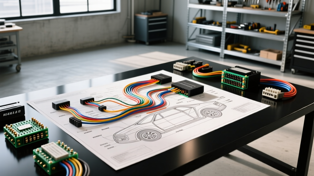
The Evolution of Custom Automotive Electrical Architecture
When building high-performance restomods, custom off-road rigs, or heavy-duty towing vehicles, the factory electrical system is rarely sufficient. Modern accessories—such as dual high-pressure EFI fuel pumps, 400W electric cooling fans, and active air suspension—can easily push baseline electrical demands past 150 amps. This is where the advanced wiring methodologies championed by top-tier specialists like Elliott's Auto Electric become critical. By moving away from outdated point-to-point splicing and fusible links, and adopting centralized power distribution and military-spec terminations, builders can eliminate voltage drop, parasitic draws, and catastrophic thermal failures.
This advanced technical deep dive explores the core principles of high-amperage custom harness architecture, detailing exact wire gauges, termination standards, and alternator sense routing protocols necessary for bulletproof vehicle electrical systems.
Centralized High-Amperage Distribution vs. Fusible Links
Historically, automakers relied on fusible links—short sections of wire rated two AWG sizes smaller than the protected circuit—to prevent harness fires. In high-draw custom builds, fusible links introduce unacceptable resistance and are notoriously difficult to diagnose when blown. The Elliott's Auto Electric approach replaces factory fusible links with a centralized, sealed Mega Fuse or ANL distribution block mounted directly to the starter motor or primary battery positive busbar.
By utilizing a central distribution node, you transition to a 'home-run' wiring topology. Each major subsystem (EFI, ignition, lighting, HVAC) receives a dedicated, fused feed directly from the central busbar. This isolates faults and ensures that a short in the cooling fan circuit does not collapse voltage to the ECU.
AWG Sizing and Voltage Drop Parameters
Selecting the correct wire gauge requires calculating the total length of the circuit (positive + ground return) and the maximum continuous amperage. Cross-linked polyethylene (XLPE) insulated wires like TXL, GXL, and SXL are mandatory for under-hood routing due to their high thermal resistance (up to 125°C).
| Wire Gauge (AWG) | Max Continuous Amps (Engine Bay) | Voltage Drop @ 100A (15ft Total Run) | Primary Application |
|---|---|---|---|
| 1/0 AWG | 250A | 0.15V | Battery to Starter / Main Busbar |
| 2 AWG | 200A | 0.24V | High-Output Alternator Output |
| 4 AWG | 150A | 0.38V | Central Distribution Block Feed |
| 8 AWG | 80A | 0.62V | Electric Fan Relays / Fuel Pumps |
| 10 AWG | 55A | 0.98V | Headlight High-Beam Feeds |
MIL-SPEC Terminations and Adhesive Heat Shrink Protocols
A common failure point in custom wiring is the termination. While soldering is often touted by amateurs as the gold standard, it creates a rigid joint that is highly susceptible to fatigue cracking in high-vibration automotive environments. Furthermore, solder wicks up into the wire strands, creating a stress concentration point just outside the joint. The professional standard—aligned with SAE J1128 guidelines—mandates high-pressure, gas-tight mechanical crimping using ratcheting, die-specific crimp tools.
The Dual-Wall Heat Shrink Standard
Every crimped termination must be sealed against moisture and galvanic corrosion. Standard PVC heat shrink is insufficient for under-hood applications. Builders must use dual-wall, adhesive-lined polyolefin heat shrink (often referred to as marine-grade or MIL-SPEC heat shrink). When heated to 120°C, the inner thermoplastic adhesive melts and flows into the wire strands, creating a completely waterproof environmental seal that prevents oxygen and moisture from initiating copper oxide formation (which increases resistance).
- Ring Terminal Torque: When securing 1/0 AWG or 2 AWG ring terminals to a battery isolation stud or busbar, the hardware must be torqued to manufacturer specifications (typically 60-80 in-lbs for 5/16" or 3/8" stainless steel studs) to ensure maximum surface contact area and prevent thermal loosening.
- Wire Stripping: Never use standard pinch-style wire strippers on TXL/GXL wire. Use precision cavity strippers to avoid nicking the copper strands, which reduces the cross-sectional area and creates a localized hot spot.
High-Output Alternator Upgrades and Remote Sense Routing
Upgrading to a 200A+ alternator (such as a GM CS144, Denso SC14, or modern Leece-Neville heavy-duty unit) requires more than simply bolting it to the bracket. The factory charge wire is usually inadequate, and the internal voltage regulator requires precise signal inputs to maintain system voltage. According to the Mad Electrical Remote Sensing Guide, failing to properly route the remote sense wire is the leading cause of under-charging in custom builds.
GM CS144 / Denso Pinout and Wire Specifications
For a standard 4-pin GM-style regulator (P-L-I-S or P-L-F-S configurations), the wiring architecture must be configured as follows:
- Pin S (Sense): This is the most critical pin. It must be connected to the main 12V distribution busbar or the positive battery terminal using 16 AWG or 14 AWG wire. It draws virtually zero current but measures the exact voltage at the vehicle's primary load center. If wired to the alternator output stud, the regulator will overcharge the battery to compensate for voltage drop across the harness.
- Pin L (Lamp/Exciter): Requires a 18 AWG wire routed through a 194-bulb (or equivalent 12V/50-ohm resistor) to a switched 12V ignition source. This provides the initial excitation current to wake up the alternator's rotor field.
- Pin I (Ignition - Optional): Used in some configurations to provide a secondary switched 12V source via 18 AWG wire to ensure the regulator remains active during cranking.
- Main Output (BATT Stud): Must be wired with 2 AWG or 1/0 AWG XLPE wire directly to the battery positive or the central Mega Fuse distribution block, bypassing the factory ammeter shunt to prevent melting the factory harness.
Advanced Voltage Drop Testing Protocol
Even with perfect wire sizing, a single corroded bulkhead connector or loose ground strap can cripple a custom electrical system. The definitive test for harness integrity is the under-load voltage drop test. This must be performed with the engine running, all high-draw accessories (fans, headlights, fuel pumps) energized, and the battery fully charged.
- Set a digital multimeter (DMM) to the DC Volts setting (mV range preferred).
- Place the positive probe on the alternator BATT output stud and the negative probe on the positive battery post. A reading above 0.20V indicates excessive resistance in the positive charge cable or its terminations.
- Place the positive probe on the battery negative post and the negative probe on the alternator case (not the bracket, the bare metal case). A reading above 0.10V indicates a poor engine-to-chassis or chassis-to-battery ground path.
- Test each individual connector in the EFI or ignition circuit by placing the DMM probes on either side of the connector while the circuit is active. Any single connection showing a drop greater than 0.05V requires terminal extraction, cleaning, and re-crimping.
By adhering to these rigorous architectural standards, builders ensure that the vehicle's electrical foundation is as reliable and high-performing as its powertrain. Whether you are integrating a standalone ECU or wiring a dual-alternator towing setup, treating the electrical system with the same precision as engine machining is the hallmark of a professional-grade build.