The Reality of Midwest Auto Electric Environments
Building a reliable vehicle in the American Midwest requires acknowledging a brutal reality: the climate is actively hostile to automotive electrical systems. A standard midwest auto electric upgrade project cannot simply replicate coastal or southern builds. Sub-zero winter temperatures thicken engine oil, increasing starter cranking resistance by up to 40%, while simultaneously reducing battery chemical efficiency by 30%. Furthermore, the aggressive use of magnesium chloride (MgCl2) and sodium chloride (NaCl) road salts creates highly conductive, corrosive brines that rapidly degrade factory aluminum ground straps and copper terminals.
When planning an upgrade and modification project for a daily driver, plow truck, or overland rig in the salt belt, marine-grade standards must be applied to automotive applications. This guide details a comprehensive 220-amp alternator upgrade, a heavy-duty Big 3 grounding protocol, and the specific termination methods required to survive Midwest winters.
Phase 1: High-Output Alternator & Main Charge Wire Specifications
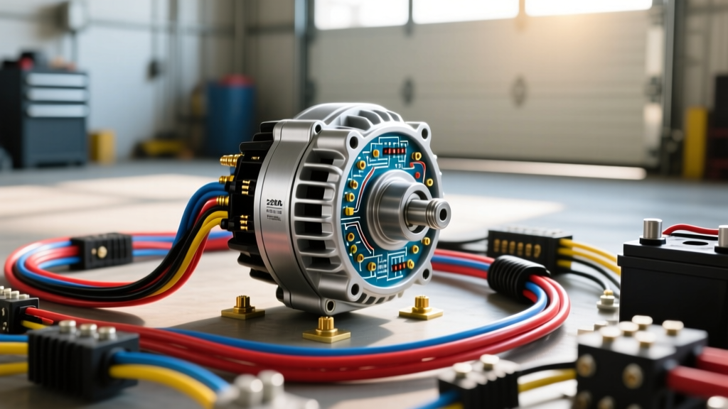
Factory alternators on popular Midwest workhorses (such as the GMT800 Silverado/Sierra or Ford Super Duty platforms) typically output between 105A and 130A. This is insufficient for modern accessory loads, including heated seats, rear defrosters, snowplow hydraulic pumps, and auxiliary lighting. Upgrading to a 220A billet alternator (such as the Mechman Elite series) requires replacing the factory 8 AWG or 6 AWG charge wire with heavy-gauge oxygen-free copper (OFC).
Do not use Copper-Clad Aluminum (CCA) wire. CCA has higher electrical resistance, is prone to galvanic corrosion when terminated at copper lugs, and becomes brittle in extreme cold, leading to catastrophic snapping under engine vibration. Always specify OFC wire with Cross-Linked Polyethylene (XLPE) insulation, which withstands under-hood temperatures up to 150°C and resists abrasion far better than standard PVC.
| Circuit | AWG Size | Material | Insulation | Terminal Type | Torque Spec |
|---|---|---|---|---|---|
| Alternator to Battery (+) | 1/0 AWG | OFC | XLPE (150°C) | 3/8" Ring, Tinned | 85 in-lbs (Battery Post) |
| Alternator Case to Block | 2 AWG | OFC | XLPE (150°C) | 5/16" Ring, Tinned | 37 lb-ft (M10 Bolt) |
| Engine Block to Chassis | 2 AWG | OFC | XLPE (150°C) | 3/8" Ring, Tinned | 65 lb-ft (M12 Bolt) |
| Battery (-) to Chassis | 2 AWG | OFC | XLPE (150°C) | 3/8" Ring, Tinned | 65 lb-ft (M12 Bolt) |
Phase 2: GM CS130D / CS144 Pinout & Voltage Sense Routing
The GM CS130D and CS144 alternators are ubiquitous in Midwest fleets. When upgrading to a high-output variant of this platform, the 4-pin connector must be rewired to handle the increased signaling and voltage sense requirements. The factory harness often suffers from voltage drop due to aging bulkhead connectors, causing the alternator's internal regulator to overcharge the battery to compensate, which boils the electrolyte in summer and damages AGM batteries in winter.
According to Mechman Alternators technical documentation, the voltage sense wire must be routed directly to the battery positive terminal or the main distribution block, completely bypassing the factory harness. Below is the precise pinout for the CS130D 4-pin connector.
| Pin | Function | Wire Color (OEM) | Upgrade AWG | Routing & Notes |
|---|---|---|---|---|
| L (1) | Lamp / Exciter | Brown/White | 18 AWG | Connects to ignition switch via 50-ohm resistor. Excites the regulator field. |
| I (2) | Ignition | Pink | 18 AWG | Switched 12V source. Wakes the regulator. Do not connect to constant 12V. |
| S (3) | Voltage Sense | Red | 16 AWG | CRITICAL: Route directly to Battery (+). Fuse at 10A within 18 inches of battery. |
| F (4) | Field / PWM | Gray | 18 AWG | PWM signal to PCM. Allows ECU to command idle bump when high loads are detected. |
Phase 3: Combating Road Salt - Terminal Sealing & Corrosion Mitigation
The most common failure point in a midwest auto electric build is not the wire itself, but the termination. Road salt brine wicks into standard heat shrink via capillary action, turning the copper strands into a solid block of green copper oxide (verdigris) within a single winter. To prevent this, you must use a strict marine-grade termination protocol.
Step-by-Step Environmental Sealing Protocol
- Strip and Clean: Strip the 1/0 AWG XLPE insulation using a precision wire stripper. Do not nick the copper strands, as nicks create stress risers that snap in sub-zero vibration.
- Hex-Indent Crimping: Insert the tinned copper ring terminal. Use a hydraulic hex-indent crimper. Avoid hammer-crimpers or dot-indent tools, which leave voids inside the barrel where moisture can pool.
- Adhesive Heat Shrink Application: Slide a 3:1 shrink ratio, dual-wall adhesive-lined heat shrink tube (such as 3M or Ancor marine grade) over the termination. The tube should cover the entire terminal barrel and overlap the wire insulation by at least 1 inch.
- Heat and Seal: Apply heat evenly with a heat gun until the shrink is tight and the internal thermoplastic adhesive purges slightly from both ends. This creates a watertight, airtight seal that completely blocks MgCl2 intrusion.
- Conductive Anti-Seize: Before bolting the terminal to the battery post or grounding stud, apply a liberal layer of NO-OX-ID A-Special grease. Unlike standard dielectric grease (which is an insulator), NO-OX-ID is electrically conductive and prevents galvanic corrosion between dissimilar metals (e.g., copper lugs and steel chassis bolts).
Phase 4: Starter Circuit Upgrades for Deep Freeze Cranking
At 0°F, a 5W-30 synthetic oil behaves like molasses, demanding massive cranking amperage from the starter motor. Factory starter feed cables are often undersized for modified engines or extreme cold. Upgrading the starter feed to 2/0 AWG OFC wire ensures maximum voltage delivery to the starter solenoid. Furthermore, the factory starter trigger wire (often 14 AWG) can suffer from voltage drop across the ignition switch and neutral safety switch, resulting in a weak solenoid engagement and starter gear grinding. Installing a heavy-duty starter relay (such as a Painless Performance 40A continuous duty relay) triggered by the factory wire ensures full battery voltage reaches the starter solenoid instantly.
Validation: Load Testing and Voltage Drop Diagnostics
After completing the alternator and grounding upgrades, the system must be validated under load. Relying on a simple multimeter resting voltage test is insufficient. You must perform a dynamic voltage drop test across all new connections. According to SAE J1128 standards and general automotive electrical best practices, voltage drop limits are strict:
- Positive Feed (Alternator to Battery): Maximum 0.2V drop under full 220A load.
- Ground Circuits (Big 3): Maximum 0.1V drop per connection under full cranking or charging load.
- Starter Feed: Maximum 0.5V drop during cold cranking.
To test, set your digital multimeter to DC Volts. Place the red probe on the alternator output post and the black probe on the battery positive post. Rev the engine to 2,500 RPM with the headlights, rear defroster, and blower motor on HIGH (simulating a 150A+ load). If the meter reads more than 0.2V, your 1/0 AWG crimp or terminal interface has excessive resistance and must be re-terminated.
Summary of the Midwest Build Philosophy
A successful midwest auto electric modification project prioritizes environmental sealing and heavy-gauge conductivity over aesthetic wire looms. By utilizing 1/0 AWG OFC charge wires, precise GM CS130D voltage sense routing, marine-grade adhesive heat shrink, and conductive anti-seize compounds, you create an electrical architecture capable of surviving the brutal thermal cycling and chemical corrosion of the American salt belt. For further reading on heavy-duty wiring schematics, consult the Painless Performance wiring manuals for relay integration and auxiliary load management.