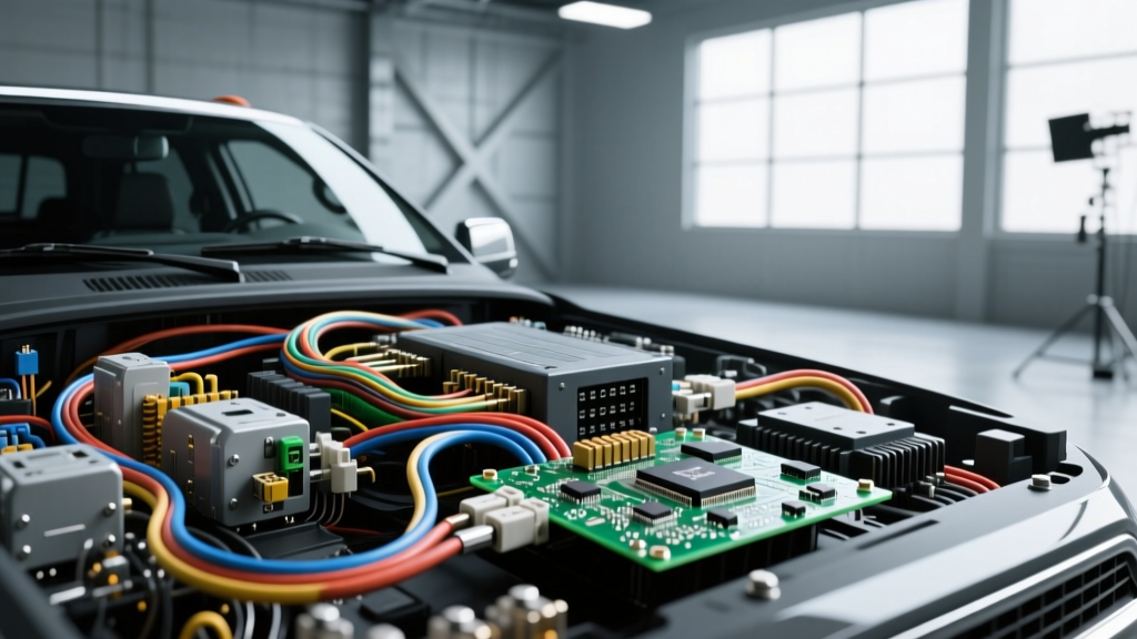
The High Cost of Incorrect CAN Bus Splicing
The Dallas-Fort Worth metroplex is notorious for its extreme summer heat, which already puts immense thermal strain on vehicle electrical systems. When DIY enthusiasts attempt to install aftermarket telematics, GPS trackers, or custom lighting by splicing directly into the Controller Area Network (CAN) bus, they often trigger catastrophic module failures. A simple wiring error can fry the Gateway Module (GWM) or the Body Control Module (BCM), resulting in a dead truck and an emergency search for an Oak Cliff auto electric repair specialist. Modern vehicles are not simple 12-volt DC circuits; they are rolling LAN networks. Understanding the physics of data transmission is critical before you pick up a wire stripper.
Anatomy of the F-150 Dual-CAN Network
Late-model Ford F-150 trucks (2015-present) utilize a complex dual-CAN architecture to separate critical powertrain data from standard body and comfort functions. This prevents a fault in the power window module from disabling the anti-lock braking system. The two primary networks are the High-Speed CAN (HS-CAN) and the Medium-Speed CAN (MS-CAN). Both networks rely on differential signaling, where data is transmitted as the voltage difference between two wires (CAN-High and CAN-Low). This differential design is meant to reject Common Mode Noise (EMI) generated by the alternator and ignition coils, but it requires strict adherence to wiring geometry.
| Network | Primary Function | CAN-H Color | CAN-L Color | Recessive/Dominant Voltage | Termination |
|---|---|---|---|---|---|
| HS-CAN | Powertrain, ABS, PCM | White | White/Blue | 2.5V / 3.5V & 1.5V | 120 Ohms (x2) |
| MS-CAN | Body, HVAC, Lighting | White/Green | White/Violet | 2.5V / 3.0V & 2.0V | 120 Ohms (x2) |
Fatal DIY Mistakes That Destroy Modules
When a DIY telematics installation goes wrong, the resulting cascade of U-codes and dead modules usually ends with a flatbed tow to a specialist for an emergency Oak Cliff auto electric repair. Here are the most common technical blunders that cause irreversible damage.
Mistake 1: Using U-Tap or Scotch-Lok Connectors on Data Lines
The most frequent mistake is using mechanical U-Tap (Scotch-Lok) connectors to tap into the CAN bus. These connectors pierce the wire insulation and rely on a metal blade to make contact. On a 22 AWG data wire, this blade severs nearly 40% of the copper strands, drastically increasing resistance. More importantly, it creates an unterminated 'stub' or 'pigtail' in the wiring harness. According to the SAE J2284 Standard for High-Speed CAN, any stub longer than 30 centimeters causes severe signal reflection. The bouncing data waves corrupt the frame checksums, forcing the modules into a 'Bus Off' state to protect themselves, which effectively shuts down the network.
Mistake 2: Ignoring Twisted Pair and Shielding Requirements
CAN bus wires are not standard power wires; they are a precisely twisted pair (typically 1 twist every 1 to 2 inches). This twisting ensures that any electromagnetic interference (EMI) from the alternator's AC ripple affects both wires equally, allowing the transceiver to cancel the noise out. DIYers often untwist the wires to make splicing easier, or they use standard 18 AWG unshielded primary wire to extend a harness. This destroys the differential noise rejection. If you must splice a CAN wire, you must use 22 AWG shielded twisted pair (STP) cable and MIL-Spec solder sleeves (such as Raychem SO96-100) that include a grounding braid to maintain the Faraday cage effect.
Mistake 3: Altering the OBD2 DLC Pinout and Ground Offsets
Many aftermarket GPS trackers plug into the 16-pin Data Link Connector (DLC). The HS-CAN lines are located at Pin 6 (CAN-H) and Pin 14 (CAN-L). Some installers attempt to hardwire devices by splicing into the back of the DLC. However, they often neglect the Signal Ground (Pin 5). If a device references Chassis Ground (Pin 4) instead of Signal Ground, and the chassis ground strap (G101, located near the battery tray) is corroded or loose, a voltage offset occurs. Ground strap G101 must be cleaned and torqued to exactly 9 Nm (80 lb-in). A loose ground introduces a voltage offset that the CAN transceivers interpret as data errors, leading to parasitic battery drains as modules fail to enter sleep mode.
Advanced Diagnostic Decision Tree
When troubleshooting a suspected CAN bus failure caused by a bad splice or aftermarket device, follow this structured diagnostic path before replacing expensive modules. These steps align with ASE L1 Advanced Engine Performance diagnostic protocols.
| Symptom / DTC | Probable Cause | Diagnostic Step & Fix |
|---|---|---|
| U0100 (Lost Comm with ECM) | HS-CAN short to ground or voltage | Disconnect battery. Measure resistance between OBD2 Pin 6 and 14. Should read ~60 ohms. If 0 ohms, locate short. If 120 ohms, one terminator is missing. |
| Parasitic Draw (>50mA) | CAN bus noise preventing module sleep | Use an oscilloscope on Pin 6 & 14. Look for asymmetrical voltage spikes. Remove aftermarket DLC devices and re-test. |
| Intermittent Stalling / Dash Flicker | Signal reflection from long stub wire | Inspect aftermarket splices. Remove Scotch-Loks. Solder connections using shielded 22 AWG wire and heat-shrink braid sleeves. |
Proper Telematics Integration: The Gateway Method
The only safe way to extract data from the F-150's CAN bus for aftermarket accessories is by using a galvanic isolation gateway module (such as an iDatalink Maestro or a standalone CAN bus isolator). These devices read the OBD2 PID data via Pins 6 and 14, process it internally, and output standard 12V logic signals or secondary, isolated CAN networks for your accessories. This ensures that no physical, electrical continuity exists between the vehicle's critical HS-CAN network and the aftermarket wiring, completely eliminating the risk of backfeeding voltage or creating impedance mismatches. For detailed OEM wiring schematics and connector pinouts, technicians should always consult Ford Motorcraft Service Information before cutting a single wire.
When to Call the Professionals
Automotive electrical architecture has evolved far beyond simple relay circuits and fuse boxes. If your F-150 is exhibiting multiple warning lights, a no-crank condition, or a severe parasitic battery drain after an attempted DIY wiring project, the damage to the network topology may require proprietary Ford IDS (Integrated Diagnostic Software) to reset the module bootloaders and clear the permanent DTCs. Attempting to 'guess and check' with a multimeter on a multiplexed network can lead to further shorting. Recognizing your limits and seeking out a certified Oak Cliff auto electric repair facility equipped with OEM-level oscilloscopes and factory scan tools is the most cost-effective way to save your truck's electrical nervous system.