The Physics Behind Auto Electrical Works
Entering the world of auto electrical works can feel like learning a foreign language, but every circuit in your vehicle obeys the same fundamental laws of physics. At its core, automotive wiring relies on the relationship between Voltage (V), Current (Amps), and Resistance (Ohms), defined by Ohm's Law (V = I x R). A standard vehicle operates on a nominal 12-volt system. However, a healthy resting battery measures exactly 12.6 volts, while the alternator's charging output should sit strictly between 13.5 and 14.5 volts. Understanding this baseline is the first step in diagnosing any electrical fault.
Current (Amperage) is the actual volume of electrons flowing through a conductor, while resistance is the friction opposing that flow. In auto electrical works, excessive resistance is the enemy. It manifests as heat, melted connectors, and dim lighting. Your primary goal when designing, repairing, or modifying a circuit is to minimize resistance while ensuring the wire gauge and fuse rating are perfectly matched to the load's amperage draw.
Decoding the Standard Automotive Relay (DIN 72552)
Relays are the workhorses of modern vehicle electrical architecture, allowing a low-current switch (like a steering column stalk) to control a high-current load (like cooling fans or headlights). Most vehicles use ISO mini or micro relays governed by the DIN 72552 standard. Memorizing these pin numbers is mandatory for anyone performing auto electrical works:
- Pin 30 (Common): The main high-current power feed directly from the battery or fuse box.
- Pin 87 (Normally Open): The output to the load. Power flows here only when the relay coil is energized.
- Pin 87a (Normally Closed): Outputs power when the relay is at rest. Often used in alarm or starter-kill circuits.
- Pin 86 (Coil Power): Receives the 12V+ trigger signal from the ignition switch or ECU.
- Pin 85 (Coil Ground): Completes the low-current control circuit to chassis ground or an ECU ground driver.
Pro Tip: When testing a relay circuit, always verify that Pin 86 receives full battery voltage (12.6V) and Pin 85 has a clean, zero-ohm path to ground before condemning the relay itself.
SAE Wire Sizing and Color Code Standards
Undersized wiring is a leading cause of electrical fires and voltage drop. The Society of Automotive Engineers (SAE) outlines strict guidelines for low-tension primary cable in the SAE J1128 standard. Unlike household wiring, automotive wire uses stranded copper for vibration resistance and specialized insulation (GXL or TXL) rated for high temperatures and chemical exposure. Below is a foundational reference chart for selecting the correct American Wire Gauge (AWG) based on circuit amperage and length (assuming a standard 10-15 foot run):
| AWG Size | Max Amps | Typical Application | Common SAE Color Code |
|---|---|---|---|
| 18 AWG | 10A | ECU Sensors, Relay Coils, Dashboard LEDs | Green / White |
| 16 AWG | 13A | Horns, Interior Dome Lights, Cigar Lighter | Dark Blue |
| 14 AWG | 15A | Tail Lights, Radio Memory, Fuel Pump Relay | Light Blue / Yellow |
| 12 AWG | 20A | Power Windows, Wipers, Ignition Feed | Purple / Brown |
| 10 AWG | 30A | HVAC Blower Motor, ABS Modules, Headlights | Orange / Red |
| 8 AWG | 50A | Alternator Main Feed, High-Current Cooling Fans | Black / Red |
| 4 AWG | 100A+ | Starter Motor, Battery Main Cables, Winches | Red (Positive) / Black (Negative) |
Note: While aftermarket stereo wiring uses a different color standard (Yellow=Constant, Red=Switched, Black=Ground), factory OEM harnesses strictly adhere to SAE or manufacturer-specific color matrices. Always consult a factory service manual before splicing into an OEM harness.
Connector Architecture: Weather-Pack vs. Metri-Pack
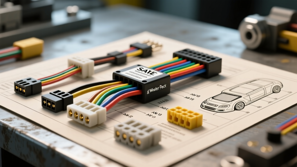
The environment under the hood is hostile, characterized by extreme heat, water ingress, and constant vibration. Standard household butt connectors will fail rapidly here. Professional auto electrical works require sealed, locking connectors. The two most prevalent systems are Delphi (now Aptiv) Weather-Pack and Metri-Pack.
Weather-Pack Series
Recognizable by their bulky, ribbed silicone seals, Weather-Pack connectors are the gold standard for under-hood accessories like auxiliary lights, winches, and aftermarket sensors. They utilize 1500 and 2800 series terminals (named for their width in thousandths of an inch). Pin 1 is always identified by a raised rib on the connector housing or an 'A'/'1' stamp near the cavity. Always use a dedicated Weather-Pack crimping tool (such as the Delphi HT-100 or equivalent ratcheting crimper) to form the wire and insulation crimps simultaneously, followed by inserting the silicone plug seal to ensure IP67 waterproofing.
Metri-Pack Series
Modern OEM ECUs, fuel injectors, and wheel speed sensors rely on Metri-Pack 150 and 280 series connectors. These are much denser, utilizing 'pull-to-seat' or 'push-to-seat' locking mechanisms. When repairing a Metri-Pack harness, you must use a specialized terminal extraction tool to depress the primary and secondary locking tangs without damaging the delicate housing.
The Art of the Crimp and Terminal Termination
A common beginner mistake in auto electrical works is relying on solder for mechanical joints. While solder conducts electricity well, it creates a rigid, brittle connection. In a high-vibration automotive environment, a solder-only joint will eventually work-harden, crack, and fail. The National Institute for Automotive Service Excellence (ASE) strictly recommends mechanical crimping using ratcheting tools that ensure the exact compression ratio for the terminal barrel.
For environmental sealing, abandon standard vinyl electrical tape. Instead, use adhesive-lined polyolefin heat shrink tubing (often called marine-grade or dual-wall heat shrink). When heated, the inner thermoplastic adhesive melts and flows into the wire strands, creating a 100% waterproof, airtight seal that blocks capillary action and prevents green copper corrosion.
Diagnostic Fundamentals: Mastering the Voltage Drop Test
When a circuit fails, beginners often replace parts blindly. Experts perform a voltage drop test. A standard multimeter measuring 12V at a corroded connector can be misleading because the meter draws virtually zero current. However, when a 15-amp load (like a fuel pump) attempts to pull current through that same corrosion, the resistance causes a massive voltage drop.
How to Perform a Voltage Drop Test
- Set your Multimeter: Switch to DC Volts (20V scale).
- Load the Circuit: The circuit MUST be active and under load (e.g., turn the headlights on, or crank the engine).
- Test the Positive Side: Place the red meter lead on the battery positive post and the black lead on the load's positive terminal. A healthy circuit should show a voltage drop of no more than 0.1V to 0.2V. Anything higher indicates high resistance (corrosion, loose crimp, or undersized wire).
- Test the Ground Side: Place the red lead on the load's ground terminal and the black lead directly on the battery negative post. The acceptable drop here is even stricter: 0.1V maximum.
According to diagnostic standards outlined in advanced automotive electrical textbooks and Delphi Connection Systems guidelines, over 70% of all 'dead' electrical components are actually victims of 'ground rot'—corrosion at the chassis grounding point where the factory ring terminal meets painted or rusted sheet metal. Always scrape down to bare, shiny metal and apply dielectric grease over the terminal after torquing it to spec.
Summary of Best Practices
Mastering auto electrical works requires patience, the right tooling, and respect for the physics of the 12-volt system. Always calculate your total amperage draw before selecting a wire gauge, use ratcheting crimpers with sealed connectors, and rely on voltage drop testing rather than visual inspections. By adhering to SAE standards and OEM-level termination practices, you will build wiring harnesses that survive the harsh realities of the road for decades.