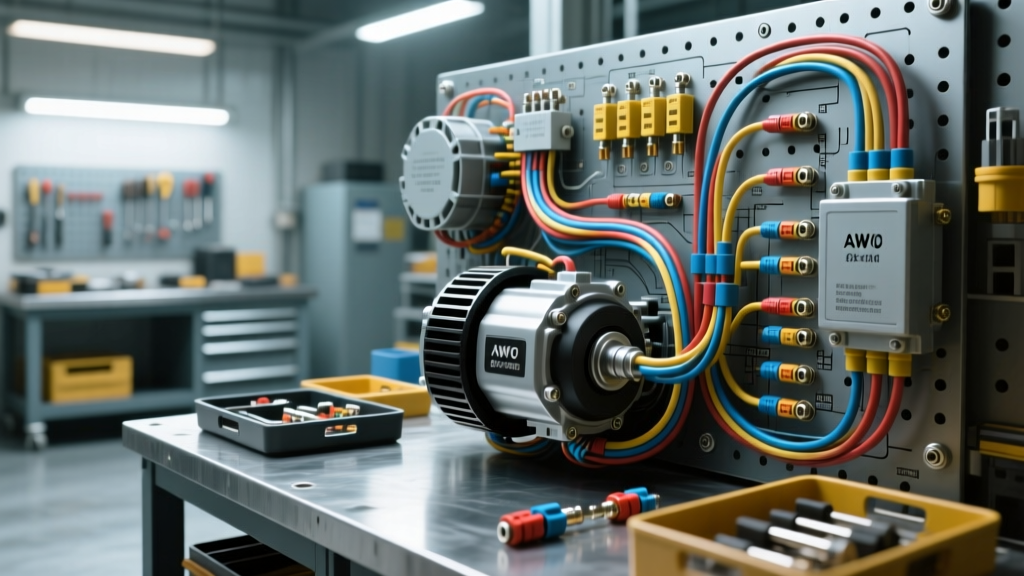
Beyond the Basics: High-Current Architecture in Modern Vehicles
When tackling advanced diy car electrical projects, the factory wiring harness is often the weakest link. Most enthusiast guides stop at swapping relays or upgrading headlight bulbs. However, when you introduce electric water pumps, high-pressure EFI fuel pumps, electric steering racks, or massive audio amplifiers, the OEM 12V architecture quickly reaches its thermal and electrical limits. A stock 105-amp alternator and 6-AWG charge wire simply cannot sustain a 220-amp continuous load without severe voltage drop and eventual thermal failure.
This deep dive bypasses elementary 12V theory and focuses on the engineering realities of high-amperage automotive circuits. We will cover high-output alternator integration, starter circuit voltage drop mitigation, and the precise termination techniques required to ensure your high-current upgrades survive the harsh underhood environment.
Upgrading the Alternator Charge Circuit
Upgrading to a high-output alternator (200A to 350A) requires a complete reevaluation of the charge wire. The OEM charge wire is typically sized with a 30% duty cycle in mind, meaning a 120A alternator might only use an 8-AWG or even 10-AWG wire from the alternator output stud to the battery positive terminal. Pushing 250 amps through a 10-AWG wire will cause the insulation to melt and the voltage at the battery to drop below 13.2V, starving your ECU and ignition system.
AWG Sizing for High-Amperage Charge Wires
According to SAE J1128 standards for battery cable, wire sizing must be calculated based on maximum continuous current and the total length of the cable run (positive and negative combined). To maintain a voltage drop of less than 0.2V across the charge circuit, use the following specifications for fine-strand copper welding cable:
| Alternator Output | Minimum AWG (Under 6 ft) | Minimum AWG (6-10 ft) | Cross-Sectional Area |
|---|---|---|---|
| 150A - 180A | 2 AWG | 1/0 AWG | 33.6 mm² - 53.5 mm² |
| 200A - 250A | 1/0 AWG | 2/0 AWG | 53.5 mm² - 67.4 mm² |
| 275A - 350A | 2/0 AWG | 4/0 AWG | 67.4 mm² - 107.2 mm² |
Always route the new charge wire away from exhaust manifolds and sharp chassis edges. Use split-loom tubing and secure it with UV-resistant zip ties every 8 inches to prevent vibration-induced work hardening of the copper strands.
OEM Regulator Pinouts: The GM CS130/CS144 Deep Dive
When retaining the OEM wiring harness plug for a high-amp upgrade, understanding the regulator pinout is critical. Many DIYers incorrectly wire the exciter circuit, leading to alternators that fail to 'wake up' at idle. The MAD Enterprises technical archives provide excellent documentation on the ubiquitous GM CS130 and CS144 4-pin connectors. Here is the exact pin configuration you must adhere to:
- Pin L (Lamp/Exciter): This is the most critical pin. It provides the initial 12V excitation current to the rotor field coil to start the charging process. It also grounds through the dash 'ALT' or 'GEN' warning lamp. If your aftermarket alternator requires an exciter wire, connect a 10-AWG switched 12V source here, ideally with a 56-ohm resistor or a standard incandescent dash bulb in parallel to prevent backfeeding.
- Pin I (Ignition): Optional on most setups. Provides a secondary switched 12V signal to ensure the regulator is fully awake during high-load cranking scenarios.
- Pin F (Field/Fault): Outputs a Pulse Width Modulated (PWM) signal representing the alternator's field duty cycle. Advanced EFI systems (like Holley Terminator X or Haltech) can read this 5V square wave to monitor alternator health and trigger a limp-mode if charging fails.
- Pin P (Phase): Taps directly into the stator windings, outputting an AC voltage proportional to alternator RPM. Historically used for electric choke relays or tachometer signals.
Starter Circuit Voltage Drop and the Solenoid Bypass
The starter motor is the highest current-drawing component in any vehicle, regularly pulling 250 to 400 amps during initial cranking. OEM starter cables are notorious for internal corrosion; the copper strands turn green and black beneath the insulation, dramatically increasing resistance. A voltage drop test across the OEM positive cable during cranking should read no more than 0.2V. If it reads 0.5V or higher, the cable must be replaced.
Implementing a Continuous-Duty Solenoid Bypass
Modern EFI systems and aftermarket engine management units (EMUs) are highly sensitive to voltage fluctuations. If the voltage at the ECU drops below 9.0V during cranking, the ECU may reset, cutting fuel and spark. The OEM ignition switch is often tasked with carrying the 30-40 amp 'pull-in' current required to engage the starter's heavy-duty solenoid. This causes massive voltage drop at the starter 'S' terminal.
To fix this, implement a solenoid bypass using a Ford-style continuous-duty relay (e.g., Motorcraft SWX-88 or equivalent):
- Mount the heavy-duty relay on the firewall or inner fender, close to the battery.
- Run a dedicated 8-AWG wire from the battery positive terminal to the relay's common terminal (Pin 30).
- Run a new 8-AWG wire from the relay's normally open terminal (Pin 87) directly to the starter's 'S' (Start) terminal.
- Splice into the OEM 'S' wire (the one coming from the ignition switch) and connect it to the relay's coil trigger terminal (Pin 86).
- Ground the relay's other coil terminal (Pin 85) to a clean chassis point.
Now, the OEM ignition switch only needs to supply less than 1 amp to trigger the relay coil, while the heavy 8-AWG bypass wire delivers full battery voltage directly to the starter solenoid, ensuring lightning-fast cranking and stable ECU voltage.
The Return Path: Grounding Architecture and Termination
Electrons do not disappear; they must return to the source. A high-amp alternator is useless if the ground path is restricted. The industry-standard 'Big 3' upgrade involves replacing or supplementing the alternator case-to-engine, engine-to-chassis, and battery-negative-to-chassis ground wires with 1/0 AWG or 2/0 AWG cable.
Surface Preparation and Hardware Specs
The most common failure point in DIY grounding is poor surface preparation. Paint, powder coat, and clear coat are electrical insulators. You must sand the grounding surface down to bare, shiny metal using 80-grit sandpaper or a wire wheel. After securing the ground, coat the entire terminal and exposed metal with a high-quality dielectric grease or marine-grade anti-corrosion compound to prevent galvanic corrosion.
Use serrated flange nuts or star washers to bite into the metal, ensuring a vibration-proof connection. Adhere to the following torque specifications for ground studs to prevent stripping the aluminum engine block or chassis threads:
- 5/16" Hardware (M8): 15 - 18 ft-lbs
- 3/8" Hardware (M10): 25 - 30 ft-lbs
- 1/2" Hardware (M12): 45 - 55 ft-lbs
Professional Termination Techniques
Never use hammer crimpers or pliers for high-current automotive wiring. A poor crimp leaves air pockets inside the terminal barrel, leading to arcing, heat buildup, and eventual failure. Invest in a 6-ton hydraulic crimper with hex-indent dies. Hex-indent crimping applies uniform, 360-degree pressure, cold-welding the copper strands to the terminal barrel.
After crimping, seal every termination with 3:1 shrink-ratio, dual-wall polyolefin heat shrink tubing. The inner layer of thermoplastic adhesive melts and flows into the wire strands, creating a completely waterproof, airtight seal that prevents capillary action from drawing moisture under the insulation. For connections exposed to extreme heat (such as near exhaust headers), use Raychem DR-25 or equivalent elastomeric heat shrink rated for continuous 150°C operation.
Summary of Best Practices
Mastering advanced automotive wiring requires respecting the physics of electricity. By calculating voltage drop, utilizing SAE-spec fine-strand copper, understanding OEM regulator pinouts, and executing flawless hydraulic crimps, you transform a fragile factory harness into a bulletproof, high-current power distribution network. Whether you are wiring a 300-amp alternator for a competition car audio system or upgrading the starter circuit on a high-compression V8, these engineering principles ensure your vehicle starts, runs, and charges reliably under the most demanding conditions.