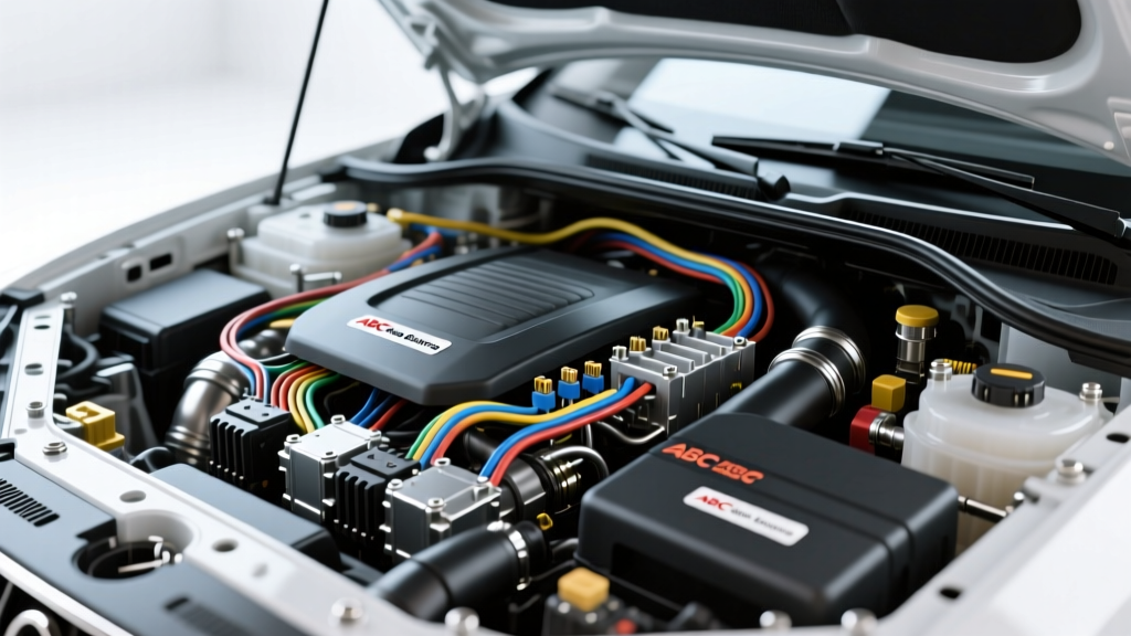
The Anatomy of Aftermarket vs. OEM Electrical Components
When sourcing replacement components for complex vehicle charging and cranking systems, many technicians and fleet managers turn to distributors like ABC Auto Electrics for cost-effective alternatives to dealer-direct OEM parts. However, evaluating ABC Auto Electrics inventory against original equipment specifications requires more than just matching part numbers and external casting dimensions. Modern vehicle electrical architecture relies heavily on precise voltage regulation, pulse-width modulation (PWM) feedback, and high-amperage thermal management. Selecting the wrong remanufactured or new aftermarket unit can trigger cascading diagnostic trouble codes (DTCs), overheat wiring harnesses, or lead to premature battery failure.
This comprehensive selection guide breaks down the critical engineering differences between standard aftermarket offerings and OEM electrical components, focusing on alternator regulator logic, starter motor architecture, and wiring harness integrity. Whether you are upgrading a heavy-duty truck charging system or restoring a classic car's cranking circuit, understanding these technical nuances ensures reliable, long-term performance.
Alternator Selection: Stator Windings and Regulator Logic
The alternator is the heart of the vehicle's electrical system. While an ABC Auto Electrics catalog might list a 145-amp alternator as a direct fit for a 2008 Chevrolet Silverado with a 5.3L V8, the internal voltage regulator and stator winding configuration dictate how the Powertrain Control Module (PCM) interacts with the unit. Many budget aftermarket alternators reuse older, simpler regulator designs inside modern housings, which bypasses the PCM's charging control algorithms.
Decoding the AD244 4-Pin Regulator Connector
General Motors vehicles from the late 1990s through the 2010s predominantly use the Delco Remy AD244 or CS130D alternator series. These units utilize a 4-pin connector to communicate with the PCM. When selecting a replacement from any auto electrical supplier, you must verify that the regulator supports all four terminals, not just the physical plug shape.
- Pin 1 (L - Lamp): The PCM provides a 12V reference to turn on the dashboard battery lamp. The regulator senses this voltage to wake up and begin charging. If an aftermarket regulator lacks internal resistance on this circuit, it can backfeed the PCM, causing a no-start condition.
- Pin 2 (I - Ignition): An optional 12V ignition source used on older applications to ensure the regulator is active during cranking.
- Pin 3 (F - Field): This is the most critical pin for modern diagnostics. The regulator sends a PWM signal back to the PCM indicating the current duty cycle of the rotor field coil. If an ABC Auto Electrics replacement unit uses a cheaper regulator that omits the 'F' terminal feedback, the PCM will immediately set a P0620 (Generator Control Circuit Malfunction) or P0562 (System Voltage Low) code, even if the alternator is outputting 14.2 volts.
- Pin 4 (P - Phase): Tied directly to the stator windings, this provides a phase tap used internally by the regulator to monitor rotor speed and occasionally by the PCM for tachometer reference.
| Terminal | Wire Color (Typical GM) | Signal Type | Aftermarket Failure Mode |
|---|---|---|---|
| 1 (L) | Red or Brown | 12V Reference / Wake-up | Backfeeding PCM; Dash lamp stays illuminated |
| 2 (I) | Pink | 12V Ignition Switched | Delayed charging initiation after cold start |
| 3 (F) | Gray or Green | PWM Feedback (5V/12V Square Wave) | Triggers P0620; PCM disables AC compressor |
| 4 (P) | Black or Purple | AC Stator Phase Tap | Erratic idle RPM; Tachometer dropouts |
Starter Motor Architecture: PMGR vs. Direct Drive
Cranking systems have largely transitioned from heavy, direct-drive starters to Permanent Magnet Gear Reduction (PMGR) units. PMGR starters use high-torque neodymium magnets and a planetary gear set to deliver immense cranking torque while drawing fewer amps and weighing significantly less. When comparing OEM starters to aftermarket equivalents, the quality of the magnets and the solenoid contactors are the primary points of divergence.
Solenoid Terminals and Cable Sizing
High-quality OEM PMGR starters utilize copper contactors inside the solenoid to bridge the B+ battery terminal to the motor windings. Inferior aftermarket units often use steel or brass contactors, which generate excessive heat and voltage drop under the 250+ amp load of cranking a cold, high-compression engine. Furthermore, the wiring harness must be sized correctly to support the specific Cold Cranking Amps (CCA) demand of the starter.
According to SAE J1128 standards for low-tension primary cables, voltage drop must be minimized to ensure adequate starter RPM. A standard 12V cranking circuit should never experience more than a 0.5V total drop from the battery positive post to the starter B+ terminal under load.
| Engine Application | Estimated Cranking Amps | Minimum Cable AWG (Up to 6ft) | Minimum Cable AWG (Over 6ft) | Max Allowable Voltage Drop |
|---|---|---|---|---|
| 4-Cyl / Small V6 Gas | 120A - 150A | 6 AWG | 4 AWG | 0.50V |
| V8 Gas / Light Diesel | 180A - 250A | 4 AWG | 2 AWG | 0.50V |
| Heavy Duty Diesel (Dual) | 400A - 600A+ | 1/0 AWG | 2/0 AWG | 0.25V per cable |
When wiring the solenoid trigger circuit (the 'S' terminal), never rely on the factory ignition switch to carry the full solenoid pull-in current (often 15-20 amps). As detailed in the Haynes Automotive Electrical Manual, installing a 30-amp Bosch-style relay triggered by the ignition switch and fed directly by a fused 10 AWG battery line ensures the solenoid receives a full 12V, eliminating the dreaded 'single-click' no-crank symptom caused by voltage drop across an aging ignition switch.
Wiring Harness Integrity and Terminal Selection
Selecting the right alternator or starter is only half the battle; the connectors linking them to the vehicle harness are equally critical. Auto electrical suppliers provide a vast array of pigtails and connector kits, but technicians must differentiate between sealed and unsealed environments, as well as terminal metallurgy.
Metri-Pack vs. Weather-Pack Sealing Standards
For under-hood alternator and sensor connections, the Aptiv (formerly Delphi) Metri-Pack 280 series is the industry standard. When sourcing replacement pigtails from ABC Auto Electrics or similar vendors, ensure the kit includes the correct silicone secondary locks and cable seals. Using a standard unsealed spade terminal in an engine bay environment will lead to galvanic corrosion within weeks, increasing resistance and triggering PCM voltage rationality faults.
Referencing Aptiv's connector engineering guidelines, the Metri-Pack 280 series is rated for up to 20 amps per circuit, making it ideal for the alternator 'L' and 'F' terminals. However, the main charge wire (B+) requires a heavy-duty ring terminal, typically crimped onto 8 AWG or 4 AWG wire using a closed-barrel hex crimp tool. Never use solder on high-amperage B+ connections; solder has a lower melting point than copper and will flow under the high-heat conditions generated by a 150-amp continuous load, leading to catastrophic joint failure.
Installation Torque and Grounding Protocols
Even the highest quality OEM electrical component will fail prematurely if installed without adhering to strict torque and grounding protocols. The alternator case serves as the primary ground path back to the engine block and battery negative. If the mounting brackets are painted, powder-coated, or corroded, the alternator will attempt to ground through the small 'I' or 'L' circuit wires, instantly melting the harness.
Critical Torque Specifications
- Alternator Mounting Bolts (M10x1.5): Torque to 37 lb-ft (50 Nm). Over-tightening can crack the cast aluminum housing, while under-tightening allows the unit to vibrate, snapping the internal stator leads.
- Starter Mounting Bolts (M10 or 3/8-16): Torque to 35 lb-ft (47 Nm). Shims must be used on older GM blocks to ensure proper Bendix drive gear mesh with the flexplate. Improper mesh results in a high-pitched whine and shattered starter noses.
- Alternator B+ Terminal Nut: Torque to 80-100 in-lbs (9-11 Nm). Warning: Over-tightening the B+ nut is the most common cause of cracked rear insulator blocks, which allows the charge wire to short directly against the alternator case, causing an un-fusible electrical fire.
Diagnostic Checklist for Aftermarket Installations
Before finalizing any installation using components sourced from ABC Auto Electrics or other aftermarket distributors, perform this mandatory validation sequence:
- Open Circuit Voltage Test: Verify battery resting voltage is above 12.6V. A surface charge of 13.2V indicates a failing cell that will mask alternator output issues.
- Parasitic Draw Test: With the vehicle asleep (modules dormant), verify draw is below 50mA. Aftermarket regulators with poor internal diode isolation can leak 200mA+ to ground, draining the battery overnight.
- Loaded Voltage Drop (Positive): Place the multimeter in DC Volts. Connect the red probe to the alternator B+ post and the black probe to the battery positive post. Rev the engine to 2000 RPM with headlights and HVAC on full. The reading must be less than 0.5V.
- Loaded Voltage Drop (Negative): Connect the red probe to the alternator case (bare metal) and the black probe to the battery negative post. Under the same load, the reading must be less than 0.1V. If higher, clean the mounting brackets and install a dedicated 8 AWG braided ground strap.
By rigorously comparing internal architecture, terminal configurations, and material quality, technicians can confidently integrate aftermarket auto electrical components into modern, computer-controlled vehicle networks without sacrificing reliability or drivability.