Planning the Mobile Auto Electric Power Architecture
When configuring a modern service vehicle, the electrical demands of on-site diagnostics, induction heaters, mobile tire changers, and heavy-duty lighting far exceed factory specifications. Building a reliable mobile auto electric workstation requires a fundamental redesign of the vehicle's power architecture. The factory 12-volt system, typically equipped with a 150-amp to 220-amp alternator and a single lead-acid starter battery, is designed primarily for engine cranking and basic ECU operation. It is not engineered to sustain the continuous 1,500-watt to 3,000-watt inverter loads required by professional mobile auto electric service rigs.
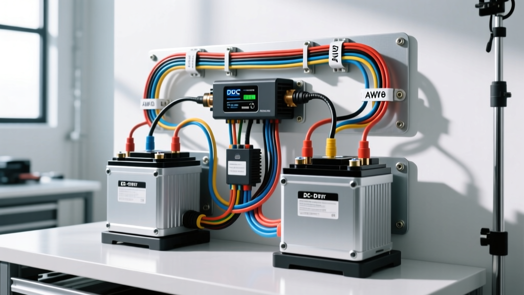
To support high-draw mobile equipment without risking strandings or ECU brownouts, technicians must implement an isolated dual-battery system managed by a DC-DC smart charger. This upgrade ensures that the auxiliary house bank powering your inverters and tools is charged efficiently, while the primary cranking battery remains protected. Furthermore, modern trucks (2015 and newer) utilize PCM-controlled 'smart alternators' that vary output voltage between 12.4V and 14.9V based on engine load and temperature. Traditional voltage-sensitive relays (VSRs) fail under these variable conditions, making a multi-stage DC-DC charger mandatory for any contemporary mobile auto electric upgrade.
Component Selection for High-Draw Mobile Workstations
Before routing a single wire, you must calculate the maximum continuous and transient amperage of your mobile auto electric tooling. A standard 2,000W pure sine wave inverter operating at 12V DC will draw approximately 166 amps continuously, and up to 250 amps during transient motor-startup surges (like when powering an air compressor or heavy-duty diagnostic cart). Therefore, the auxiliary battery bank and interconnecting wiring must be sized for a 300-amp baseline.
According to SAE J1128 standards for low-tension primary cable, wire sizing must account for both amperage and the physical length of the wire run to mitigate voltage drop. For a service truck where the auxiliary bank is mounted in the bed or rear cargo area (typically 15 to 20 feet from the alternator), voltage drop becomes a critical failure point if undersized cables are used.
Wire Gauge and Overcurrent Protection Matrix
| Circuit Segment | Max Amperage | Wire Gauge (AWG) | Wire Type | Overcurrent Protection |
|---|---|---|---|---|
| Alternator to Starter Battery | 320A (Upgraded) | 1/0 AWG | SAE J1128 Type SGT | 350A ANL Fuse |
| Starter Battery to DC-DC Charger | 50A (Input) | 6 AWG | Stranded Tinned Copper | 60A Mega Fuse |
| DC-DC Charger to Aux Bank | 25A (Output) | 8 AWG | Stranded Tinned Copper | 30A ATC Breaker |
| Aux Bank to 2000W Inverter | 200A Cont. / 300A Peak | 2/0 AWG | Flexible Welding Cable | 250A Class T Fuse |
Step-by-Step Wiring: Alternator to Auxiliary Bank
Step 1: Upgrading the Alternator Output Circuit
Most factory alternators are wired with 4 AWG or 2 AWG wire, which will overheat and melt if you upgrade to a 320-amp high-output alternator (such as a Mechman or Power Bastards unit). You must run a dedicated 1/0 AWG SGT wire directly from the alternator B+ terminal to the positive post of the primary starter battery. Install a 350A ANL fuse within 7 inches of the battery positive terminal. Use military-spec lead-coated copper terminal clamps and crimp them using a hex-die hydraulic crimper to ensure a gas-tight connection. Seal the crimp barrel with dual-wall adhesive-lined heat shrink to prevent moisture ingress and copper oxidation.
Step 2: Smart Alternator Ignition Sense Routing
To wake up the DC-DC charger and signal the smart alternator to output maximum voltage, you need a clean 12V ignition source. Do not splice into the vehicle's CAN-bus or sensitive ECU wiring. Instead, locate the upfitter switch module or the ignition run circuit in the fuse box. Run a 14 AWG yellow wire from this circuit to the DC-DC charger's blue ignition sense wire. Install a 5A inline ATC fuse holder near the tap point to protect the sense circuit from shorting to ground.
Step 3: DC-DC Charger Installation and Pinout
Mount the DC-DC charger (e.g., REDARC BCDC1225D) in a ventilated area, preferably inside the cabin or a protected utility box. These units generate significant heat during the bulk charging phase. Wire the input and output according to the manufacturer's specifications, ensuring all ground wires are terminated to a single, unified bus bar rather than daisy-chained to random chassis points.
DC-DC Charger Pinout and Connection Matrix
| Pin / Wire Color | Function | Connection Destination | Notes |
|---|---|---|---|
| Red (Heavy) | DC Input Positive | Starter Battery (+) | Via 60A Mega Fuse |
| Black (Heavy) | DC Input Negative | Main Ground Bus Bar | Do not use chassis ground |
| Red (Light) | DC Output Positive | Aux Battery Bank (+) | Via 30A ATC Breaker |
| Black (Light) | DC Output Negative | Main Ground Bus Bar | Keep parallel to output positive |
| Blue | Ignition Sense / Trigger | 12V IGN Run Circuit | Via 5A Inline Fuse |
| Green | Temperature Sensor | Aux Battery Negative Post | Required for LiFePO4/AGM profiling |
Auxiliary Battery Bank and Inverter Integration
For a mobile auto electric setup requiring 2,000W+ of continuous AC power, a single 100Ah AGM battery is insufficient due to Peukert's Law, which drastically reduces effective capacity under high-draw conditions. The optimal configuration is a parallel bank of two 100Ah Lithium Iron Phosphate (LiFePO4) batteries. LiFePO4 chemistry maintains a flat voltage curve (13.4V - 13.6V) even under heavy load, preventing the inverter's low-voltage cutoff from triggering prematurely.
When wiring batteries in parallel, use identical lengths of 2/0 AWG interconnecting cables to ensure equal resistance across the bank. Connect the main inverter feed to the positive terminal of Battery A and the negative terminal of Battery B. This 'diagonal wiring' method balances the current draw across both batteries, preventing one battery from doing all the heavy lifting while the other sits idle.
The inverter must be mounted as close to the auxiliary bank as possible—ideally within 3 feet. The DC input wiring for a 3,000W inverter requires 2/0 AWG flexible welding cable. Protect this circuit with a 250A Class T fuse. Class T fuses are specifically designed to handle the massive DC arc flashes that occur if a high-capacity lithium bank shorts out, a risk that standard ANL or Mega fuses cannot safely mitigate.
Grounding Protocols and SAE Standards
A common failure in mobile auto electric modifications is relying on the vehicle's sheet metal for high-amperage return paths. Modern truck beds and cargo areas are often isolated by rubber body mounts and bed liners, creating high-resistance ground loops. According to best practices aligned with Blue Sea Systems circuit protection guidelines and ABYC/SAE standards, all high-current DC returns (alternator, inverter, DC-DC charger) must be routed via dedicated copper cables back to a centralized, heavy-duty brass ground bus bar. This bus bar should then be tied directly to the negative post of the starter battery using a 1/0 AWG ground cable. Never use self-tapping screws into sheet metal for grounds exceeding 10 amps; always use through-bolts with star washers on bare, paint-stripped metal, coated with dielectric grease post-torque.
Troubleshooting Voltage Drop Under Load
Even with perfect wire sizing, mobile environments introduce vibration, thermal cycling, and corrosion. If your mobile auto electric tools are underperforming, or the inverter shuts down under load, perform a systematic voltage drop test.
Symptom-Cause-Fix Decision Tree
- Symptom: Inverter alarms at 10.5V DC when drawing 1,200W AC, but multimeter at battery reads 12.8V.
Cause: Excessive voltage drop on the positive or negative DC feed to the inverter.
Fix: Check all crimp connections. A poorly crimped lug will show a voltage drop greater than 0.1V under load. Re-crimp with a proper hex die and apply heat shrink. - Symptom: Auxiliary bank fails to charge while driving; DC-DC charger shows no input.
Cause: Smart alternator is in 'eco-mode' (outputting 12.4V), and the ignition sense wire is losing voltage.
Fix: Verify the blue ignition sense wire is reading a solid 12V+ with the key in the 'Run' position. If the smart alternator drops voltage, you may need to install an alternator override module or reprogram the BCM via an OBD-II tuning tool to force 'Tow/Haul' charging profiles. - Symptom: Alternator B+ terminal is melting or discolored.
Cause: The 1/0 AWG upgrade wire was not torqued to spec, creating micro-arcing and localized heat.
Fix: Cut off the damaged terminal. Clean the alternator stud with a wire brush. Install a new tinned lug and torque to 12 ft-lbs. Apply a dab of terminal protector spray.
By adhering to these stringent wiring protocols, AWG calculations, and isolation strategies, your mobile auto electric service vehicle will deliver uninterrupted, clean power to your diagnostic and repair equipment, ensuring professional efficiency in any remote or roadside environment. For further reading on DC-DC charging profiles for specific battery chemistries, consult the REDBARC DC-DC Charging Architecture Guidelines to ensure your auxiliary bank achieves maximum cycle life.