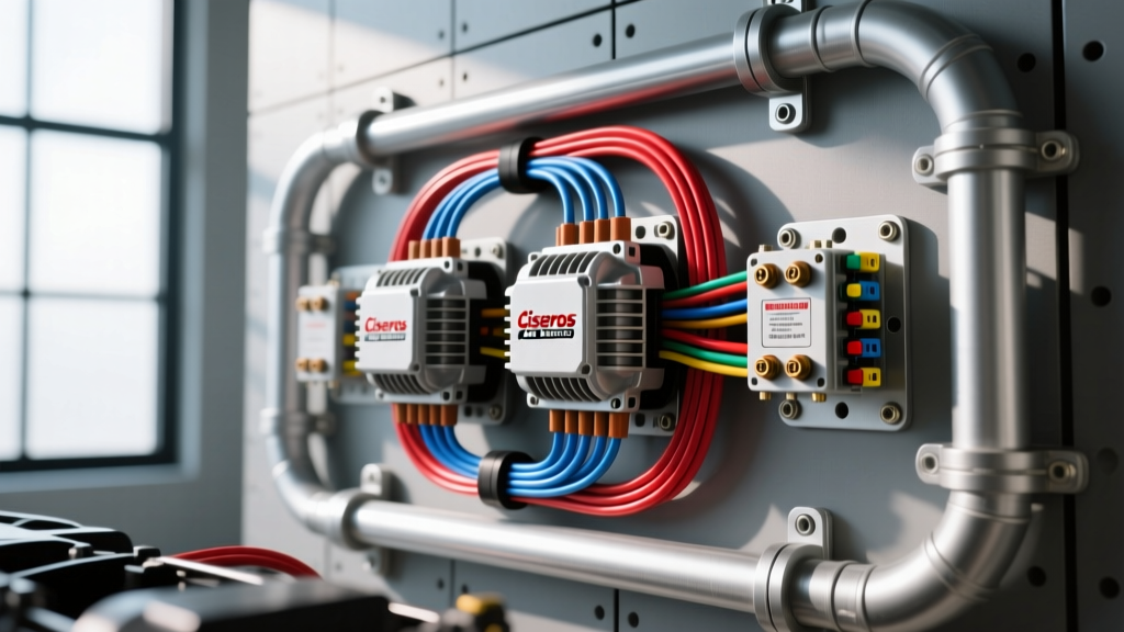
Introduction to the Cisneros Auto Electric Standard
When outfitting heavy-duty fleet vehicles, expedition rigs, and mobile command centers, standard OEM electrical systems fall drastically short of modern power demands. The methodology championed by Cisneros Auto Electric has become a benchmark in the custom automotive electrical industry for designing redundant, high-amperage dual alternator systems. Unlike basic auxiliary battery setups, the Cisneros Auto Electric standard focuses on minimizing voltage drop, eliminating ground loops, and ensuring precise regulator sense routing in systems pushing 400 to 600 continuous amps.
This advanced technical deep dive explores the core wiring architecture, cable sizing protocols, and termination standards required to execute a heavy-duty dual alternator build according to these rigorous fleet specifications.
High-Amperage Dual Alternator Architecture
The foundation of the Cisneros Auto Electric methodology relies on pairing a primary OEM-style alternator with a secondary high-output, heavy-duty alternator (typically a Delco Remy 40SI or 50SI brushless model rated for 250A to 300A). The primary alternator handles standard chassis loads and ECU requirements, while the secondary alternator is dedicated exclusively to auxiliary battery banks, winches, and high-draw inverters.
To manage the massive current transfer, main B+ and ground runs must be calculated not just for peak amperage, but for continuous thermal limits and acceptable voltage drop over the physical length of the cable run. According to SAE J1128 standards for low-tension primary cables, high-amp routing requires specialized insulation to withstand under-hood thermal cycles.
Main Cable Routing and Sizing Specifications
| Circuit Function | AWG Size | Strand Count / Type | Insulation Rating | Max Length (One Way) | Max Voltage Drop |
|---|---|---|---|---|---|
| Secondary Alt B+ to Busbar | 1/0 AWG | 4234 / 30 AWG Copper | XLPE (125°C) | 48 inches | < 0.25V @ 250A |
| Busbar to Aux Battery Bank | 2/0 AWG | 6654 / 30 AWG Copper | XLPE (125°C) | 72 inches | < 0.30V @ 250A |
| Main Engine Block Ground | 2/0 AWG | 6654 / 30 AWG Copper | EPDM (150°C) | 36 inches | < 0.10V @ 500A |
| Chassis to Aux Battery Neg | 1/0 AWG | 4234 / 30 AWG Copper | EPDM (150°C) | 60 inches | < 0.15V @ 250A |
Alternator Regulator Pinouts and Sense Wiring
A critical failure point in high-amp builds is improper voltage sense routing. If the internal or external regulator reads voltage from the alternator's B+ terminal rather than the actual battery post, the voltage drop across the main cable will cause the alternator to overcharge, boiling the electrolyte and destroying the battery bank. The Cisneros Auto Electric protocol mandates a dedicated, fused sense wire.
Delco Remy 4-Pin Regulator Connector Breakdown
For heavy-duty brushless alternators utilizing the standard 4-pin Delco connector, the following pin configuration and wire color codes must be strictly adhered to:
- Pin 1 (L - Lamp/Indicator): 18 AWG Brown wire. Routed to a dashboard LED indicator with a 470-ohm current-limiting resistor. This pin provides the initial excitation voltage required to 'turn on' the alternator field.
- Pin 2 (S - Battery Sense): 10 AWG Red wire with an inline 15A MAXI fuse. Crucial: This wire must be routed directly to the positive post of the auxiliary battery bank, completely independent of the main 1/0 AWG B+ cable. This ensures the regulator compensates for voltage drop across the main charging cable.
- Pin 3 (F - Field/Tachometer): 18 AWG White wire. Used for diagnostic pulse-width monitoring or routed to a digital tachometer interface to monitor alternator RPM and belt slip.
- Pin 4 (I - Ignition): 14 AWG Pink wire. Connected to a clean, switched 12V ignition source (e.g., the run side of the ignition switch or a keyed relay). This wakes the internal microprocessor.
Dual Battery Isolation and Solenoid Control
To prevent the auxiliary loads from draining the primary starting battery, the Cisneros Auto Electric standard utilizes a heavy-duty continuous duty solenoid rather than standard diode isolators, which suffer from a 0.7V forward voltage drop and massive heat dissipation issues at 200+ amps.
The recommended component is the Cole Hersee 24063 continuous duty solenoid (rated for 250A continuous). The coil control circuit for this solenoid requires specific wiring to prevent voltage spikes from destroying the vehicle's ECU or body control module (BCM).
Solenoid Coil Wiring Protocol
- Run a 14 AWG Blue wire from the ignition-switched 12V source to the solenoid's positive coil terminal (Terminal 86).
- Connect the negative coil terminal (Terminal 85) to a dedicated, clean chassis ground using 14 AWG Black wire.
- Transient Suppression: Install a 1N5408 flyback diode across the coil terminals (cathode to positive, anode to negative) to absorb the inductive kickback when the ignition is turned off. Alternatively, use a bidirectional TVS diode for solid-state isolation.
Termination, Crimping, and Environmental Sealing
High-amperage circuits generate significant heat at points of resistance. A poorly crimped 1/0 AWG ring terminal will act as a resistor, generating enough heat to melt standard PVC insulation and cause a chassis fire. The Bosch Automotive Electrics guidelines emphasize the necessity of gas-tight crimps in high-current environments.
The Cisneros Auto Electric methodology requires the following termination steps:
- Stripping: Use a calibrated cable stripper to expose exactly 1-1/8 inches of copper, ensuring zero nicked or cut strands.
- Fluxing: Apply a non-corrosive, rosin-based electrical flux to the exposed copper strands to prevent oxidation during the crimping process.
- Hydraulic Crimping: Use a 12-ton hydraulic crimper with the exact matching hex die for the specific terminal manufacturer (e.g., Ilco or Burndy). A 1/0 AWG terminal typically requires a die marked '1/0' or color-coded Pink/Yellow depending on the brand.
- Sealing: Slide a piece of 3/8-inch dual-wall, adhesive-lined MIL-spec heat shrink over the joint before crimping. After crimping, apply heat evenly from the middle outward until the inner adhesive melts and extrudes slightly from the edges, creating a waterproof, airtight seal against galvanic corrosion.
Troubleshooting High-Amperage Ripple and Ground Loops
Even with perfect wire sizing, dual alternator systems can introduce severe AC ripple voltage into the DC system if the grounding architecture is flawed. This ripple can cause audio system whine, flickering LED lighting, and erratic sensor readings.
Ripple Voltage Diagnostic Tree
| Symptom / Reading | Probable Cause | Cisneros Standard Corrective Action |
|---|---|---|
| AC Ripple > 50mV (measured at battery) | Failed alternator rectifier diode bridge. | Bench test alternator; replace rectifier assembly or complete unit. |
| AC Ripple spikes under load; EMI noise in cabin | Alternator case not bonded to engine block. | Install a dedicated 4 AWG braided copper ground strap from the alternator casing mounting ear directly to the engine block. |
| Erratic voltage regulation (swings 13.2V to 15.1V) | Voltage drop on the Pin 2 (Sense) wire. | Check the 15A inline fuse on the 10 AWG Red sense wire. Verify connection is directly on the battery lead post, not on a busbar. |
| Solenoid chatters rapidly at idle | Undersized coil ground or voltage drop on ignition feed. | Upgrade solenoid coil feed to 12 AWG and ensure ground is on bare, unpainted chassis metal with a star washer. |
Conclusion
Executing a dual alternator upgrade requires moving beyond basic wire-and-connect tactics. By adopting the Cisneros Auto Electric methodology—prioritizing dedicated sense circuits, utilizing XLPE-insulated 1/0 and 2/0 AWG cabling, enforcing hydraulic gas-tight crimps, and managing inductive kickback—technicians can build fleet-grade electrical systems capable of sustaining 500+ amps reliably in the harshest environments. Always verify all high-amp connections with a thermal imaging camera after a 20-minute loaded idle test to ensure no localized hotspots exceed ambient temperature by more than 15°C.