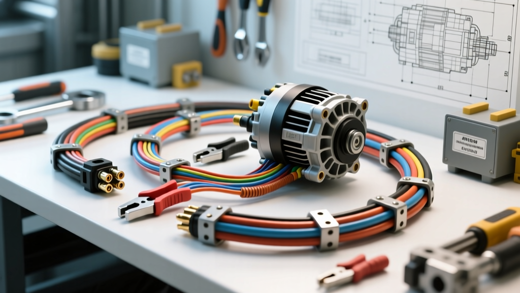
Introduction to the Zapotlan Auto Electric Methodology
The Zapotlan Auto Electric methodology originated from advanced vocational heavy-duty repair programs in Jalisco, Mexico, designed specifically to combat extreme electrical degradation in high-altitude, high-ambient-temperature commercial fleet environments. Today, the Zapotlan Auto Electric protocol is recognized globally among master commercial technicians as a premier standard for severe-duty wiring harness fabrication, alternator output upgrades, and starter circuit diagnostics. Unlike standard passenger vehicle electrical repairs, which rely on general-purpose PVC wiring and basic crimp connections, the Zapotlan protocol mandates rigorous thermal derating calculations, specialized cross-linked insulation, and aerospace-grade termination techniques to ensure zero-failure operations in Class 8 trucks and heavy agricultural machinery.
When commercial vehicles operate in environments where under-hood temperatures routinely exceed 105°C (221°F) and electrical loads push past 200 amps, standard wiring practices fail catastrophically. The Zapotlan Auto Electric standard addresses these failure modes by over-engineering the thermal resistance of the harness, optimizing voltage drop across high-amperage circuits, and implementing strict diagnostic thresholds that far exceed baseline OEM specifications.
High-Ambient Thermal Degradation in Commercial Harnesses
Standard Polyvinyl Chloride (PVC) wire insulation, commonly rated for 85°C to 105°C, undergoes severe dielectric breakdown and plasticizer migration when routed near heavy-duty exhaust manifolds, turbocharger housings, or EGR coolers. As the plasticizers leach out, the PVC becomes brittle, cracks under engine vibration, and eventually causes dead-shorts against the chassis. The Zapotlan Auto Electric protocol strictly prohibits the use of standard PVC in any primary high-amperage engine bay circuit.
XLPE and PTFE Insulation Mandates
Instead, the protocol requires Cross-Linked Polyethylene (XLPE) or Polytetrafluoroethylene (PTFE) insulated conductors. XLPE wire (often marketed as GXL or TXL in automotive applications) is rated for continuous operation at 125°C and features a significantly higher melting point and abrasion resistance than PVC. For circuits routed within 6 inches of exhaust components, the Zapotlan standard mandates PTFE (Teflon) insulated wire, which withstands continuous temperatures up to 200°C. Furthermore, all high-temperature terminations must be sealed using dual-wall, adhesive-lined polyolefin heat shrink with a minimum 3:1 shrink ratio to prevent moisture wicking into the copper strands via capillary action.
Alternator Output Circuit Upgrades (Delco Remy 40SI/50DN)
Heavy-duty trucks frequently utilize high-output alternators such as the Delco Remy 40SI (160A-200A) or the 50DN brushless series. A common failure in standard fleet maintenance is undersizing the main charge cable, leading to severe voltage drop, undercharging, and alternator diode burnout. The Zapotlan Auto Electric methodology applies a strict 20% thermal derating factor to all wire sizing calculations.
Main Charge Cable Sizing and Routing
For a 160A Delco Remy 40SI alternator, standard AWG charts might suggest 2 AWG wire. However, applying the Zapotlan thermal derating protocol for an engine bay ambient temperature of 80°C, the required wire size increases to 1/0 AWG (0 AWG) XLPE. This ensures the conductor can handle continuous 160A loads without the insulation degrading or the copper heating up and increasing resistance. The main output cable must be routed away from the alternator's internal cooling fan intake to prevent the alternator from pulling in superheated air radiating off the charge cable itself.
Precision Sense Wire Routing
The sense circuit (Terminal S on Delco Remy connectors) is critical for voltage regulation. Standard OEM harnesses often splice the sense wire into the main charge cable near the alternator, which causes the regulator to compensate for localized voltage drop rather than actual battery state-of-charge. The Zapotlan protocol dictates that the sense wire (12 AWG, Red) must be routed independently, fused at 15A within 8 inches of the battery, and terminated directly at the battery's positive post. This ensures the regulator reads true battery voltage, optimizing the charge profile for deep-cycle AGM or lithium-iron-phosphate auxiliary banks.
Zapotlan Protocol Wire Sizing and Insulation Matrix
The following matrix outlines the minimum specifications required under the Zapotlan Auto Electric standard for heavy-duty commercial charging and cranking circuits operating in high-thermal environments.
| Circuit Application | Continuous Load | Minimum AWG Size | Insulation Type | Terminal / Crimp Spec |
|---|---|---|---|---|
| Alternator Main Output (Charge) | 160A - 200A | 1/0 AWG | XLPE (125°C) | Hex-Indent Copper, 3:1 Adhesive Seal |
| Starter Motor Positive Feed | 800A - 1200A (Peak) | 4/0 AWG | XLPE or Silicone Fiberglass | Heavy-Duty Ring, Conductive Anti-Oxide |
| Alternator Sense Wire (Terminal S) | 2A - 5A | 12 AWG | GXL (125°C) | Metri-Pack 280, Gold-Plated Pin |
| ECM/BCM CAN-Bus Shielded Pair | Signal (<1A) | 18 AWG Twisted Pair | PTFE (200°C) + Foil Shield | Deutsch DT, Dedicated Drain Wire |
Starter Motor Solenoid Voltage Drop Diagnostics
Diagnosing cranking faults in heavy-duty diesel engines requires moving beyond simple battery voltage checks. A fully charged 12V battery bank might show 12.6V at rest, but under a 1000A cranking load from a 7.2L or 15L diesel engine, hidden resistances in the cables and solenoids will cause massive voltage drops, starving the starter motor of amperage and resulting in slow cranking or solenoid chatter.
Step-by-Step Millivolt Drop Testing
The Zapotlan Auto Electric diagnostic tree relies on dynamic millivolt drop testing using a high-resolution digital multimeter (such as a Fluke 88V automotive meter) set to DC millivolts. The test must be performed while the engine is actively cranking.
- Positive Side Drop: Place the red probe on the alternator output post (or battery positive) and the black probe on the starter motor main input stud. Crank the engine. According to SAE J1141 standards, the total positive side voltage drop should not exceed 0.5V. The strict Zapotlan protocol limits this to 0.3V for heavy-duty applications.
- Solenoid Internal Drop: Move the black probe to the starter motor's output side of the solenoid (the stud connecting to the motor field coils). Crank the engine. A reading above 0.1V indicates internal solenoid contact pitting or carbon buildup, mandating immediate solenoid replacement.
- Ground Side Drop: Place the red probe on the starter motor housing (unpainted metal) and the black probe on the battery negative post. Crank the engine. The Zapotlan standard allows a maximum of 0.15V total ground-side drop. Readings higher than this indicate corroded chassis ground straps or poor engine-to-frame bonding.
Advanced Grounding and Multiplexed Chassis Protocols
Heavy-duty trucks utilize the chassis and engine block as primary ground return paths. However, the introduction of rubber engine mounts and non-conductive anti-corrosion coatings severely disrupts these paths. The Zapotlan Auto Electric methodology requires dedicated, oversized braided copper ground straps for engine-to-frame bonding. Solid core or stranded wire is prohibited for primary engine grounds due to its susceptibility to work-hardening and breaking under high-frequency diesel vibration.
All grounding studs must be cleaned down to bare, bright metal using a brass wire brush or Scotch-Brite pad. The protocol mandates the use of star washers (internal or external tooth lock washers) placed between the terminal and the chassis to bite through microscopic oxide layers. Finally, after torquing the ground bolt to manufacturer specifications, the entire termination must be encapsulated in a conductive anti-oxidant grease (such as NO-OX-ID A-Special) to displace oxygen and prevent galvanic corrosion between the copper terminal and the steel chassis.
Authoritative References and SAE Standards
The methodologies outlined in the Zapotlan Auto Electric protocol are heavily derived from and validated by established automotive and heavy-duty engineering standards. For further technical validation, master technicians should consult the following authoritative resources:
- SAE J1141: The Society of Automotive Engineers standard for voltage drop testing in heavy-duty electrical systems, establishing the baseline thresholds for acceptable circuit resistance under load. (SAE International)
- Delco Remy Heavy Duty Alternator Service Manuals: Provides exact pinout configurations, sense wire routing requirements, and thermal derating charts for the 40SI and 50DN brushless alternator platforms. (Delco Remy)
- Bosch Automotive Electrics and Automotive Electronics: A comprehensive reference text detailing the physics of thermal degradation in PVC and XLPE insulation, as well as multiplexed CAN-bus shielding requirements in high-EMI environments. (Bosch Mobility Solutions)
By adhering to the rigorous material specifications, precise crimping methodologies, and strict diagnostic thresholds of the Zapotlan Auto Electric standard, fleet technicians can virtually eliminate heat-induced electrical failures, ensuring maximum uptime for severe-duty commercial vehicles.