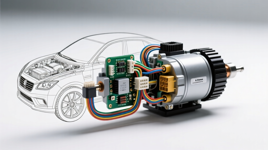
Introduction to the El Puma Heavy-Duty Electrical Platform
The Ford F-Series 'El Puma' (encompassing the F-4000 and F-14000 heavy-duty platforms widely utilized in South American commercial fleets) represents a benchmark in rugged trucking. However, as fleet operators integrate modern telemetry, high-draw LED lighting arrays, and auxiliary comfort systems, the stock auto electric infrastructure frequently reaches its thermal and operational limits. Modernizing the El Puma auto electric system requires a fundamental understanding of 24V heavy-duty architectures, voltage drop mitigation, and high-current switching. This advanced technical guide provides a comprehensive deep dive into upgrading the starter circuit, integrating high-output brushless alternators, and installing aftermarket electric AC compressors without compromising the vehicle's baseline electrical integrity.
24V Starter Circuit Architecture and Voltage Drop Mitigation
Heavy diesel platforms like the El Puma, often equipped with high-compression MWM Sprint or Cummins powerplants, require massive cranking amperage—frequently exceeding 1,200A peak—to overcome cylinder compression and cold-start friction. The factory starter circuit often suffers from excessive voltage drop due to undersized cabling, degraded bulkhead connections, and inadequate chassis grounding.
Cable Sizing and Routing Specifications
To support sustained cranking loads, upgrade the main battery-to-starter positive and negative runs to 2/0 AWG (70mm²) cross-linked polyethylene (XLPE) insulated cable. This specification ensures compliance with SAE J1128 standards for low-tension primary cables, offering superior thermal resistance up to 125°C. When routing the 2/0 AWG positive cable, maintain a minimum bend radius of 1.5 inches to prevent internal strand fracturing, which increases resistance over time.
Starter Solenoid Pinout and Relay Isolation
The heavy-duty magnetic switch on the starter motor requires a clean, high-amperage trigger signal. Factory wiring often routes this through a multi-function ignition switch, leading to contact arcing and voltage loss. Implement a dedicated starter isolation relay using a heavy-duty ISO 280 format relay rated for 75A continuous:
- Pin 86 (Coil +): Connect to the ignition switch 'Start' position via a 14 AWG wire.
- Pin 85 (Coil -): Connect to a dedicated chassis ground point using a 14 AWG wire and a star washer to bite through paint and corrosion.
- Pin 30 (Common): Receive fused 24V directly from the battery bank positive post via a 10 AWG feed wire protected by a 30A MIDI fuse.
- Pin 87 (Normally Open): Feed the starter 'S' (trigger) terminal using a 10 AWG wire.
Voltage Drop Limits: Maximum acceptable voltage drop is 0.2V per main cable and 0.1V across any single connection under a 1,000A cranking load. Use a digital multimeter in Min/Max mode across the cable ends while an assistant cranks the engine to verify compliance.
Chassis Grounding vs. Dedicated Ground Bus Architecture
A critical failure point in the El Puma auto electric system is the reliance on the truck frame and engine block as the primary ground return path. While acceptable for low-draw lighting, high-amperage 24V systems require dedicated ground returns. Install a centralized copper ground bus bar (minimum 1/4-inch thickness) mounted to the chassis rail using 3/8-inch Grade 8 hardware. Run a 1/0 AWG tinned copper ground strap from the battery bank negative terminal directly to this bus bar, and a secondary 1/0 AWG strap from the bus bar to the engine block. Apply a conductive anti-corrosion compound to the mating surfaces before torquing to 45 Nm, and seal the exterior with dielectric grease to prevent galvanic corrosion.
High-Output Alternator Integration (300A+)
Upgrading the El Puma auto electric charging system from a stock 140A unit to a 300A+ brushless alternator (such as a Leece-Neville or heavy-duty Bosch equivalent) requires precise sense-wire routing. Brushless alternators utilize internal voltage regulators that depend on an accurate remote sense signal to adjust the rotor's magnetic field. If the sense wire is routed incorrectly, the alternator will either overcharge the 24V battery bank (boiling the electrolyte) or undercharge it (leading to sulfation).
Alternator Terminal Specifications and Pin Configuration
Refer to the following specification chart when wiring a high-output 24V alternator to the El Puma platform:
| Terminal | Function | Wire Gauge | Routing & Protection |
|---|---|---|---|
| B+ | Battery Positive Output | 1/0 AWG | Direct to battery positive post, max 24 inches. Torque M10 nut to 15 Nm. |
| S (Sense) | Battery Voltage Sense | 10 AWG | Direct to battery positive post. Must include an inline 15A ATO fuse within 6 inches of the battery. |
| IG (Ignition) | Excitation Trigger | 14 AWG | Switched 24V from ignition relay. Activates the internal regulator. |
| L (Lamp) | Indicator / Field | 16 AWG | Dash warning light circuit. Requires a 470-ohm pull-up resistor if using LED dash indicators. |
Pro-Tip: Never terminate the 'S' (Sense) wire at the alternator B+ terminal or a nearby distribution block. The voltage drop across the main 1/0 AWG output cable under a 250A load can be 0.5V or more. If the sense wire reads this dropped voltage, the regulator will artificially increase output, resulting in system overvoltage. For deeper insights into heavy-duty charging principles, consult the engineering guidelines provided by Bosch Mobility Solutions.
Integrating Electric AC Compressors in Diesel Platforms
Engine-driven AC compressors introduce parasitic drag, complicate engine-swap projects, and fail prematurely under high-underhood thermal loads. Installing a high-voltage 24V electric AC compressor (such as a DENSO ES-series scroll compressor) is a premier El Puma auto electric upgrade that improves cab comfort while reducing engine load.
High-Current Contactor and Fuse Sizing
A 24V electric scroll compressor can draw 35A to 45A continuously, with startup inrush currents exceeding 120A. Standard automotive ISO relays will quickly suffer from contact welding and thermal meltdown under these conditions. Instead, utilize a heavy-duty DC contactor (e.g., Gigavac or White-Rodgers) rated for 150A continuous DC switching.
- Primary Power Circuit: Run 4 AWG primary power wire from a dedicated 150A ANL fuse block. The fuse block must be mounted within 8 inches of the battery positive terminal to protect the entire cable run in the event of a dead short.
- Compressor Ground: Run a dedicated 4 AWG ground wire directly back to the centralized ground bus bar. Do not rely on the compressor's mounting brackets for the primary ground return, as rubber vibration isolators will interrupt the circuit.
- Logic Control Circuit: The compressor's internal inverter requires a 12V/24V logic signal to engage. Use a 16 AWG shielded twisted-pair cable for the trigger signal to prevent Electromagnetic Interference (EMI) generated by the alternator's high-frequency switching and the starter motor's inductive spikes.
Diagnostic Decision Tree: Cranking & Charging Faults
When troubleshooting the El Puma auto electric system, systematic isolation is critical. Use the following decision tree to diagnose common heavy-duty electrical faults:
Symptom: Slow Cranking / Clicking Solenoid (24V System)
- Step 1: Measure voltage directly at the battery bank terminals during a crank attempt. If the voltage remains above 22V (11V per battery), the battery bank is healthy and fully charged.
- Step 2: Measure voltage at the starter B+ terminal during crank. If the reading is below 21.5V, you have high resistance in the 2/0 AWG positive cable, a corroded battery terminal, or a faulty chassis ground.
- Step 3: Measure voltage at the starter 'S' (trigger) terminal during crank. If the reading is below 18V, the fault lies in the ISO 280 relay, the ignition switch trigger circuit, or a voltage drop in the neutral safety switch wiring.
Symptom: Alternator Outputting 28.5V+ (Overcharging 24V System)
- Step 1: Immediately shut down the engine to prevent ECU damage and battery thermal runaway.
- Step 2: Check the 'S' (Sense) wire continuity from the alternator plug to the battery positive post. A broken or disconnected sense wire defaults the internal regulator to maximum field output.
- Step 3: Inspect the 15A inline ATO fuse on the sense wire. If blown, the regulator is flying blind.
- Step 4: Verify the alternator chassis ground. If the alternator casing lacks a solid ground path to the engine block, the internal regulator may misread the system voltage reference.
By adhering to these advanced wiring protocols, technicians and fleet engineers can drastically improve the reliability, cranking performance, and auxiliary capacity of the El Puma heavy-duty platform. For baseline chassis schematics and factory torque specifications, always cross-reference with official Ford Commercial Truck documentation before modifying OEM harnesses.