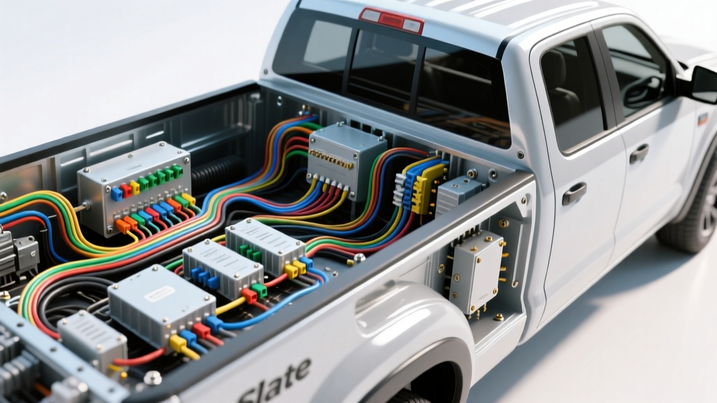
Introduction to the Slate Auto Electric Pickup Truck Architecture
The automotive landscape is undergoing a massive shift toward electrification, and the utilitarian, modular design philosophy behind the Slate Auto electric pickup truck represents the cutting edge of this evolution. For automotive technicians, DIY enthusiasts, and upfitters transitioning from internal combustion engine (ICE) vehicles to electric vehicles (EVs), understanding the underlying electrical architecture is critical. Unlike traditional trucks that rely on a single 12-volt system and an engine-driven alternator, modern EV pickups utilize a complex dual-voltage paradigm.
This beginner-friendly guide breaks down the foundational wiring concepts, safety protocols, and architectural layouts that define the Slate Auto electric pickup truck and similar modern EV platforms. Whether you are diagnosing a low-voltage phantom drain, planning an auxiliary light bar installation, or simply trying to understand the high-voltage safety interlocks, mastering these fundamentals is your first step into the world of EV electrical systems.
The Dual-Voltage Paradigm: High-Voltage vs. Low-Voltage
The most crucial concept for any beginner to grasp is the strict separation between the High-Voltage (HV) traction system and the Low-Voltage (LV) accessory system. These two systems coexist in the same chassis but serve entirely different purposes and require vastly different handling protocols.
High-Voltage (HV) Traction System
The HV system is the muscle of the Slate Auto electric pickup truck. It typically operates between 400V and 800V DC, powering the e-axles, traction motors, and the onboard AC compressor. The wiring in this system consists of heavily shielded, braided copper cables encased in a bright orange outer jacket. This shielding is not just for physical protection; it is designed to contain Electromagnetic Interference (EMI) that could otherwise disrupt the vehicle's sensitive CAN bus networks.
Connections in the HV system are handled by specialized, touch-proof connectors such as the Amphenol SurLok Plus or TE Connectivity HVCC series. These connectors feature integrated High Voltage Interlock Loop (HVIL) circuits. The HVIL is a low-voltage (usually 5V or 12V) signal wire that runs through every HV connector. If a connector is unplugged or vibrates loose, the HVIL circuit breaks, instantly signaling the Battery Management System (BMS) to open the main contactors and de-energize the cables outside the battery enclosure.
Low-Voltage (LV) Accessory and Control System
The LV system operates at a nominal 12V (or sometimes 48V in specific auxiliary circuits) and powers the vehicle's computers, lighting, infotainment, power windows, and crucially, the main HV contactors. Because EVs do not have an engine-driven alternator, the 12V auxiliary battery (increasingly a LiFePO4 lithium module rather than lead-acid) is kept charged by a DC-DC Converter.
The DC-DC converter steps down the 400V+ from the traction battery to a regulated 14.1V–14.5V output. In a heavy-duty electric pickup, the DC-DC converter is typically rated between 200A and 300A to support high electrical loads like electric power steering, regenerative braking controllers, and cabin heating. The primary output cables from the DC-DC converter to the 12V distribution bus require heavy-duty 2/0 AWG or 1/0 AWG welding cable to prevent voltage drop and thermal throttling.
Essential EV Wiring Color Codes and Safety Standards
Working on the Slate Auto electric pickup truck requires strict adherence to standardized color codes. Misidentifying a wire in an EV can be fatal or result in the destruction of expensive control modules. The color coding is governed by safety standards such as SAE J2929 and federal regulations like FMVSS 305.
| Wire Color | System / Function | Voltage Level | Technical Notes & Standards |
|---|---|---|---|
| Solid Orange | High-Voltage Power | 400V - 800V DC | Mandated by FMVSS 305. Must be shielded. Never pierce with a multimeter probe. |
| Orange w/ Yellow Tracer | HVIL Signal | 5V - 12V DC | High Voltage Interlock Loop. Breaks the circuit if an HV connector is unseated. |
| Red | Low-Voltage Battery (+) | 12V - 14.5V DC | Standard LV positive. Fed by the DC-DC converter and auxiliary battery. |
| Black | Low-Voltage Ground (-) | 0V DC | Chassis ground or dedicated LV return path. |
| Green / White Pair | CAN Bus High / Low | 2.5V / 2.5V (Differential) | Twisted pair data lines. Requires 120-ohm termination resistors at each end of the bus. |
Upfitting and Auxiliary Accessory Wiring
Pickup trucks are designed to be worked, and the Slate Auto electric pickup truck is no exception. Owners frequently want to install auxiliary LED light bars, winches, camper shells, and air compressors. However, tapping into an EV's electrical system requires more caution than in an ICE vehicle due to the absence of an alternator and the reliance on the DC-DC converter's maximum amperage output.
Calculating AWG for EV Pickup Accessories
When wiring accessories, you must calculate the wire gauge based on the maximum amperage draw and the total length of the wire run (positive + negative). Voltage drop is the enemy of EV accessories; if a winch solenoid doesn't receive adequate voltage, it will chatter and fail to engage.
| Accessory Type | Typical Amperage | Recommended AWG (Up to 10ft Run) | Recommended Fuse / Breaker |
|---|---|---|---|
| LED Light Bar (50") | 10A - 15A | 12 AWG | 20A ATO Blade Fuse |
| On-Board Air Compressor | 30A - 40A | 8 AWG | 50A MAXI Fuse |
| Electric Winch (12,000 lb) | 300A+ (Peak) | 2/0 AWG Welding Cable | 250A Circuit Breaker |
| Camper Shell Lighting | 5A | 14 AWG | 10A Mini Fuse |
Pro-Tip for EV Upfitters: Always utilize the vehicle's designated Upfitter Switches or auxiliary relay bank if equipped. Tapping directly into the DC-DC converter's main output lugs can cause ground loop interference on the LV CAN bus, leading to erratic behavior in the vehicle's battery thermal management system.
Charging Architecture and Inlet Wiring
The charging port on the Slate Auto electric pickup truck (typically utilizing the CCS1 or NACS standard) is a complex hub of both high-voltage power delivery and low-voltage communication. According to SAE J1772 standards, the charge inlet contains several critical pins beyond just the positive and negative power feeds.
- Proximity Pilot (PP): A low-voltage circuit that uses a resistor network to tell the vehicle's onboard charger exactly what amperage rating the plugged-in cable is capable of handling.
- Control Pilot (CP): A PWM (Pulse Width Modulation) signal that communicates between the EVSE (charging station) and the vehicle, negotiating the charge rate and confirming safety ground continuity before the HV contactors close.
If the CP or PP pins become corroded or bent, the vehicle will physically plug in, but the handshake will fail, resulting in a 'Charge Fault' on the dashboard. Cleaning these pins with electrical contact cleaner and a nylon brush is a common beginner-level fix.
Beginner Troubleshooting: Why Won't My EV Pickup Start?
Troubleshooting an EV pickup requires a shift in mindset. When a customer or owner complains that their Slate Auto electric pickup truck is 'dead' or won't shift into Drive, the instinct is to blame the massive high-voltage battery. In 90% of cases, the issue lies in the 12V low-voltage system.
The 12V Phantom Drain and Contactor Logic
The main HV contactors inside the battery pack are heavy-duty electromagnetic relays. They require a solid 12V signal to pull closed. If the 12V auxiliary battery drops below 11.5V due to a phantom drain (e.g., an aftermarket dashcam wired without a low-voltage cutoff, or a stuck telematics module), the BMS will not have enough power to close the main contactors. The vehicle will appear completely dead, even if the HV traction battery is at 100% State of Charge (SoC).
Diagnostic Decision Tree for 'Vehicle Not Ready'
- Check the 12V Battery Voltage: Use a multimeter on the LV battery terminals. If below 12.0V, charge or jump-start the 12V system using a dedicated 12V lithium-safe charger.
- Scan for HVIL Faults: If the 12V is healthy, connect an OBD2 EV-capable scanner. Look for 'Isolation Fault' or 'HVIL Open Circuit' codes. This indicates a loose orange HV cable, often found at the PTC heater or AC compressor.
- Inspect the MSD: Locate the Manual Service Disconnect (MSD). This is a physical safety plug that breaks the HV circuit inside the battery. Ensure it is fully seated and the locking tab is engaged.
- Verify DC-DC Converter Output: With the vehicle 'Ready to Drive', measure the voltage at the 12V battery. It should read between 13.8V and 14.5V. If it reads exactly 12.0V and dropping, the DC-DC converter has failed or is in thermal protection mode.
Conclusion
Transitioning to the Slate Auto electric pickup truck and the broader EV ecosystem doesn't require a degree in electrical engineering, but it does demand respect for the dual-voltage architecture. By understanding the separation of the HV traction system and the LV control networks, adhering to SAE color codes, and properly sizing your auxiliary wiring, you can safely maintain, diagnose, and upfit the next generation of electric work trucks. Always prioritize safety, wear appropriate PPE when working near orange cabling, and rely on verified wiring diagrams before making any modifications.