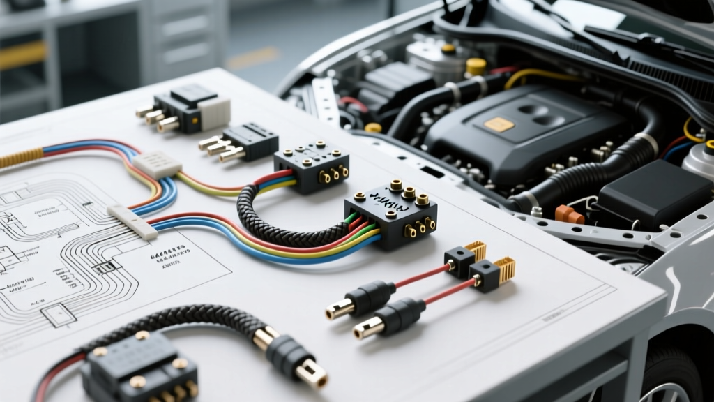
What is the LEO Auto Electric Method?
When approaching the complex wiring harness of a modern vehicle, beginners often feel overwhelmed by the sheer volume of wires, connectors, and control modules. To simplify this, industry professionals often rely on the LEO auto electric diagnostic framework. LEO stands for Live (Power Source), Earth (Ground Return), and Output (Load/Signal). By breaking every electrical circuit down into these three fundamental checkpoints, you can systematically isolate faults without guessing or throwing expensive parts at the problem.
Whether you are installing an aftermarket electric AC compressor, troubleshooting a dim headlight, or mapping out a starter circuit, the LEO methodology ensures you verify the foundation of the circuit before testing the component itself. This guide will walk you through the LEO framework with specific wire gauges, connector standards, and real-world testing parameters.
Phase 1: LIVE (Power Source and Feed Verification)
The 'Live' side of the circuit encompasses everything from the battery positive terminal to the input side of the load. In automotive applications, this means verifying that the correct voltage is reaching the component under the exact conditions required (e.g., constant 12V vs. ignition-switched 12V).
Wire Color Codes and SAE Standards
According to SAE J1128 standards, standard automotive primary wire uses specific color codes to indicate circuit function. While manufacturer variations exist, the general baseline is:
- Red or Yellow: Constant 12V battery feed (fused).
- Pink or Brown: Ignition-switched 12V (hot in Run/Start).
- Orange: Accessory circuit (hot in Acc/Run).
For high-current applications like starter motors or electric cooling fans, you must use cross-linked polyethylene insulated wire (GXL or TXL) to withstand under-hood temperatures up to 125°C.
AWG Sizing for Live Feeds
Undersized power wires cause severe voltage drop, leading to slow cranking or weak spark. Use this reference chart for continuous 12V DC loads:
| AWG Size | Max Amps (Continuous) | Typical Application |
|---|---|---|
| 18 AWG | 6A | ECU sensors, LED indicators |
| 14 AWG | 15A | Interior lighting, radio memory |
| 10 AWG | 30A | Headlights, fuel pumps, power windows |
| 8 AWG | 40A | Electric AC compressors, cooling fans |
| 4 AWG | 100A | Main alternator charge wire |
| 2/0 AWG | 200A+ | Starter motor primary cable |
Phase 2: EARTH (Ground Return Integrity)
The 'Earth' (or ground) is the return path to the battery's negative terminal. In a vehicle's unibody or body-on-frame chassis, the metal structure acts as the common ground return. Over 70% of all automotive electrical gremlins are caused by poor ground connections.
Identifying Ground Wires and Connections
Ground wires are universally Black, or Black with a White/Light Green tracer. When attaching a ground ring terminal to the chassis, you must scrape away all paint, powder coating, and rust to achieve bare metal contact. Apply a small dab of dielectric grease over the terminal after tightening to prevent oxidation.
Torque Specifications and Voltage Drop Testing
A loose ground stud creates resistance. According to Fluke's automotive testing guidelines, a healthy ground connection should exhibit a voltage drop of no more than 0.10V (100mV) under load. To test this, set your multimeter to DC Volts, place the red probe on the battery negative post (not the clamp), and the black probe on the component's ground terminal while the circuit is active.
For chassis ground studs (typically M8 or M10 flange bolts), the factory torque specification is usually between 15 Nm and 22 Nm. Always use a star washer or a serrated flange nut to bite through minor surface corrosion.
Phase 3: OUTPUT (Load, Relays, and Signals)
The 'Output' is the component doing the actual work—the headlight bulb, the starter solenoid, or the AC compressor clutch. However, high-current outputs are rarely switched directly by a dashboard button. They are controlled via relays.
Mastering the DIN 72552 Relay Pinout
Understanding the standard ISO/DIN mini relay is mandatory for any auto electrician. The Bosch automotive standard defines the following pin configurations for a standard 4-pin relay:
| Pin Number | Terminal Name | Function |
|---|---|---|
| 30 | Common Input | Constant 12V power from battery (fused) |
| 87 | Normally Open (NO) | Output to the load (e.g., compressor clutch) |
| 85 | Coil Ground | Ground path for the relay's internal electromagnet |
| 86 | Coil Power | 12V trigger signal from switch or ECU |
Pro Tip: The internal coil of a standard 12V automotive relay typically has a resistance of 60 to 90 Ohms. If you measure 0 Ohms (short) or infinite Ohms (open) across pins 85 and 86, the relay coil is dead and must be replaced.
Connector Standards: Metri-Pack vs. Weather-Pack
When repairing the Output side of a circuit, avoid splicing wires with twist-caps or electrical tape. Modern vehicles rely on sealed connector systems.
- Delphi Metri-Pack 280: The industry standard for under-hood and interior connections. The '280' refers to the blade width (2.8mm). It handles up to 30 amps and uses a secondary lock (TPA) to prevent terminals from backing out.
- Weather-Pack: Common on older GM and Chrysler vehicles. Bulkier, with a distinct rubber seal and locking tang. Excellent for high-vibration, high-moisture environments.
- Deutsch DT Series: The gold standard for heavy-duty, off-road, and aftermarket motorsport wiring. Uses solid copper crimp barrels and silicone seals.
Troubleshooting Decision Tree: The LEO Method in Action
Let's apply the LEO auto electric framework to a real-world scenario: An aftermarket electric cooling fan that will not turn on.
- Check LIVE: Use a test light on Pin 30 of the fan relay. Does it illuminate? If no, trace the 10 AWG red wire back to the fuse box. Check for a blown 30A maxi-fuse.
- Check EARTH: Check the black 14 AWG ground wire at the fan motor. Perform a voltage drop test. If you read 4.5V across the ground wire while the relay is clicked, the chassis ground is corroded. Clean and re-torque to 18 Nm.
- Check OUTPUT: Jump pins 30 and 87 on the relay harness with a heavy-duty jumper wire. If the fan spins, the motor and main power are good. The fault lies in the trigger circuit (Pins 85/86) or the thermostat switch sending the signal.
Final Thoughts for Beginners
Mastering the LEO auto electric fundamentals transforms wiring from a dark art into a logical, step-by-step science. Always verify your Live feeds with a digital multimeter (DMM), ensure your Earth connections are mechanically sound and electrically clean, and understand the internal architecture of your Output relays and loads. By respecting AWG limits and utilizing proper sealed connectors, your electrical repairs will survive the harsh vibration and temperature cycles of the automotive environment.