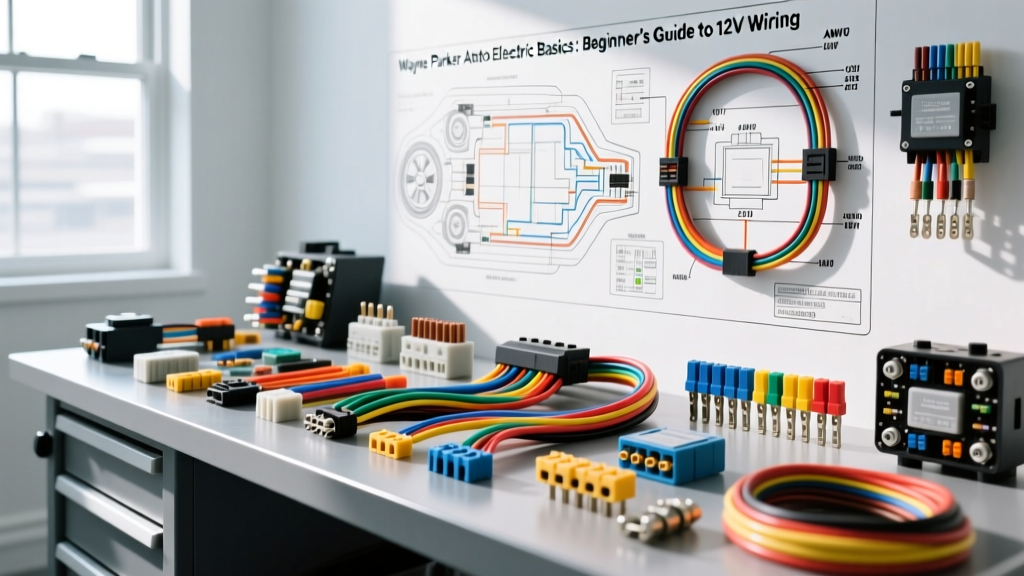
The Wayne Parker Auto Electric Philosophy for Beginners
When entering the world of automotive diagnostics, the sheer volume of wiring harnesses, control modules, and sensors can be overwhelming. The core tenet of the Wayne Parker auto electric methodology is simple: systematic, logical troubleshooting always beats random parts-swapping. For beginners, mastering the fundamentals of 12-volt DC systems is the critical first step before attempting to diagnose complex CAN bus networks or ECU faults. By understanding how electrical current flows through a vehicle, how to properly size conductors, and how to interpret relay logic, you build a foundation that makes advanced diagnostics significantly easier. This guide breaks down the essential building blocks of vehicle electrical architecture, providing actionable specifications and real-world testing procedures that every aspiring auto electrician must know.
The Realities of a Nominal 12-Volt System
The most common misconception among beginners is that a car battery supplies exactly 12 volts. In reality, a fully charged, resting lead-acid or AGM automotive battery measures between 12.6V and 12.8V. When the engine is running and the alternator is actively charging the system, that voltage rises to a regulated window of 13.8V to 14.4V. Modern vehicles with smart alternators and Battery Management Systems (BMS) may push this up to 14.8V during deceleration regenerative phases, or drop it to 12.2V during fuel-saving stop/start modes. Understanding this voltage variance is crucial when selecting components. For instance, a standard 12V halogen bulb will draw more current and burn significantly hotter at 14.4V than it will at 11.5V during engine cranking. Always base your diagnostic expectations on the actual system voltage measured at the battery terminals, not the nominal '12V' label.
SAE J1128 Wire Sizing and Insulation Types
Automotive wire is not the same as standard household copper wire. Vehicle wiring must withstand extreme temperature fluctuations, exposure to petroleum-based fluids, and constant vibration. The SAE J1128 Standard dictates the specifications for low-tension primary cable used in automotive applications. Modern vehicles primarily use cross-linked insulation types like GXL, TXL, and SXL, which offer superior heat resistance and thinner walls compared to older PVC wires, allowing for smaller, lighter harnesses without sacrificing current capacity.
Choosing the correct American Wire Gauge (AWG) is critical to prevent voltage drop and potential fire hazards. The table below outlines standard SAE primary wire sizing for typical 12V automotive circuits, assuming a standard ambient temperature of 25°C (77°F) and a maximum allowable voltage drop of 0.5V over a 10-foot circuit run.
| AWG Size | Cross-Section (mm²) | Max Continuous Amps | Common Automotive Application |
|---|---|---|---|
| 18 AWG | 0.80 mm² | 6A - 8A | ECU sensor signals, LED indicator lights, CAN bus lines |
| 16 AWG | 1.30 mm² | 10A - 12A | Interior lighting, radio memory circuits, horn relays |
| 14 AWG | 2.00 mm² | 15A - 18A | Cigarette lighter sockets, tail lights, power windows |
| 12 AWG | 3.00 mm² | 20A - 25A | Headlight high beams, fuel pump power feeds, ABS valves |
| 10 AWG | 5.00 mm² | 30A - 40A | Main accessory feeds, high-amperage cooling fan circuits |
| 8 AWG | 8.00 mm² | 50A - 60A | Alternator B+ output (short runs), aftermarket amplifiers |
| 4 AWG | 20.0 mm² | 100A - 120A | Starter motor cables, main battery-to-fuse-box feeds |
Note: When sizing wire for high-current circuits like starter motors, you must account for 'cranking amps' which can exceed 250A for brief durations. A 4 AWG or 2 AWG cable is typically required to minimize voltage drop during engine start.
Mastering the DIN 72552 Relay Standard
Relays are the workhorses of automotive electrical systems, allowing a low-current switch (like a dashboard button or ECU transistor) to control a high-current load (like a radiator fan or fuel pump). The vast majority of standard ISO mini-relays found under the hood follow the DIN 72552 terminal numbering standard. According to Bosch Mobility Solutions, understanding these specific pin designations is mandatory for any diagnostic procedure.
- Pin 30 (Common / B+): The main high-current power input, usually fed directly from the battery or a main fuse block. Wire color is typically heavy-gauge Red or Black.
- Pin 87 (Normally Open - NO): The high-current output that receives power only when the relay coil is energized. Connects to the load (e.g., headlights).
- Pin 87a (Normally Closed - NC): The high-current output that receives power when the relay is at rest. (Note: Many standard 4-pin relays omit this pin).
- Pin 86 (Coil Power): The low-current 12V+ trigger input, usually switched by the ignition, a dashboard button, or an ECU driver.
- Pin 85 (Coil Ground): The low-current ground path for the electromagnetic coil. Often controlled by the ECU to complete the circuit.
Pro-Tip for Beginners: When replacing a relay, check for an internal flyback diode or resistor between pins 85 and 86. If an ECU is triggering the ground on Pin 85, using a relay without a suppression diode can send a high-voltage inductive spike back into the ECU driver, permanently destroying the transistor.
The Voltage Drop Test: Your Ultimate Diagnostic Tool
The most common mistake beginners make is relying on continuity testing to diagnose wiring faults. A single strand of 18 AWG copper wire can show 'continuity' (near 0 ohms) on a multimeter, but it cannot carry the 15 amps required to power a fuel pump. The Wayne Parker auto electric approach heavily emphasizes voltage drop testing on live, loaded circuits to identify hidden resistance. As detailed in standard Haynes Auto Electrical Basics guides, voltage drop testing measures the exact amount of electrical pressure (voltage) lost as current pushes through a connection or wire.
Step-by-Step Voltage Drop Procedure
- Prepare the Circuit: Ensure the circuit is active and under load. Turn on the headlights or command the cooling fan to run. The circuit must be drawing its normal operating current.
- Set the Multimeter: Set your digital multimeter (DMM) to DC Volts (20V scale).
- Test the Power Side: Place the red probe on the positive battery terminal and the black probe on the power input pin of the load (e.g., the headlight bulb connector). Acceptable drop: Less than 0.2V total for the entire power side of the circuit.
- Test the Ground Side: Place the red probe on the negative terminal of the load and the black probe on the negative battery terminal. Acceptable drop: Less than 0.1V across any single ground connection or splice.
If you measure a 2.5V drop on the ground side of a headlight circuit, you have found your fault. The current is struggling to find a path back to the battery, likely due to corrosion at the chassis ground stud or a loose ring terminal. Clean the ground point, apply dielectric grease, and retest.
Grounding Architecture: Chassis vs. Star Points
Modern vehicles do not run individual ground wires back to the battery for every component. Instead, they utilize the steel chassis and engine block as a massive common ground return path. However, this architecture is highly susceptible to galvanic corrosion and paint interference. Factory grounding relies on 'star points' or centralized ground buses, often located in the cabin kick panels or engine bay fenders. When performing aftermarket installations or repairs, never rely on self-tapping screws into painted sheet metal. Always use a proper ring terminal, sand away the paint and clear coat to bare metal, secure it with a Grade 8 bolt and star washer, and seal the area with epoxy or grease to prevent moisture ingress. A poor ground doesn't just cause dim lights; it can cause erratic sensor readings, triggering false Check Engine Lights and erratic transmission shifting.
Conclusion
Mastering the Wayne Parker auto electric fundamentals requires patience and a commitment to doing things the right way. By respecting SAE wire sizing standards, understanding DIN relay logic, and religiously performing voltage drop tests instead of guessing, you will diagnose electrical faults faster and more accurately than mechanics who rely on trial and error. Keep your multimeter calibrated, your wire strippers sharp, and always verify your grounds.