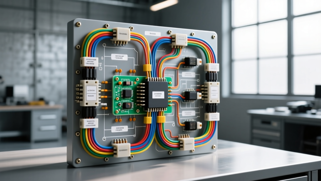
Introduction to Custom Harness Diagnostics
When diagnosing bespoke wiring systems—particularly the compact, high-efficiency layouts popularized by custom builders and methodologies like Shorty's Auto Electric—technicians must abandon stock factory manual approaches. Custom hot rods, classic trucks, and restomod builds utilize centralized power distribution blocks, high-amperage alternator feeds, and simplified grounding architectures. While these setups reduce overall harness weight and complexity, they introduce unique failure modes when terminal crimps degrade, ground straps loosen, or aftermarket relays overheat.
This guide provides a comprehensive, step-by-step troubleshooting flow designed specifically for custom automotive electrical architectures. By following this diagnostic tree, you can systematically isolate dead-crank conditions, charging system failures, and parasitic draws without resorting to guesswork or unnecessary parts swapping.
Phase 1: The Dead Crank / No-Start Decision Tree
A 'dead crank' scenario in a custom build rarely points to a failed starter motor right out of the gate. In most Shorty's Auto Electric style harnesses, the starter circuit relies on a multi-stage relay setup to protect the ignition switch from high-amperage voltage drops.
Step 1: Main Power Feed and Distribution Block Verification
- Verify Battery Voltage: Connect a digital multimeter (DMM) across the battery terminals. You must see a minimum of 12.4V (surface charge) before proceeding.
- Inspect the Main Mega-Fuse: Trace the 2 AWG or 4 AWG main battery cable to the primary distribution block. Check the 150-amp or 175-amp Mega-Fuse. Use the DMM in continuity mode to verify the fuse is intact.
- Check Distribution Block Lugs: Custom harnesses often use copper buss bars or terminal blocks. Ensure the set screws or ring terminal nuts are torqued to 8-10 ft-lbs. Loose lugs cause severe voltage drops under the 150+ amp load of a starter motor.
Step 2: Ignition Switch and Starter Solenoid Circuit
If main power is present at the distribution block, move to the starter trigger circuit.
- Ignition Feed: Check the 10 AWG red wire at the 'BAT' terminal of the ignition switch for 12V+ constant power.
- Crank Trigger: Have an assistant turn the key to 'START'. Probe the 12 AWG purple or yellow wire at the 'ST' (Start) terminal. You should read within 0.5V of battery voltage.
- Neutral Safety Switch (NSS): If voltage drops to 0V at the NSS output, check the switch adjustment. Custom column shifts often misalign the NSS plunger, breaking the 12 AWG purple wire circuit to the starter solenoid 'S' terminal.
Phase 2: Charging System & Alternator Output Flow
Custom builds frequently utilize 1-wire or internally regulated 3-wire alternators (such as the Delco 12SI or CS130 series). Improper excitation or remote sensing is the leading cause of 'no-charge' conditions in these setups.
Step 3: Testing the Alternator Excitation Circuit
- Measure Battery Voltage Running: Start the vehicle. If voltage remains at 12.2V and does not climb to 13.8V–14.4V, the alternator is not exciting.
- 1-Wire Alternator Check: 1-wire alternators require a specific RPM threshold (usually 1,500–2,000 RPM) to self-excite. Rev the engine. If it begins charging, the internal diode trio is functional, but idle charging will always fail. Upgrade to a 3-wire setup for street-driven vehicles.
- 3-Wire Alternator Check (Terminal 1 & 2): Probe Terminal 1 (L - Exciter) with the key ON, engine OFF. You must read 12V+ through the 12 AWG red/white exciter wire and the dash idiot light or resistor. If 0V, check the 10-amp fuse on the exciter circuit.
- Remote Sense Verification: Probe Terminal 2 (S - Sense). This 16 AWG wire must connect directly to the battery positive or main distribution block. If it is incorrectly jumpered to the alternator output post, the regulator will falsely read high voltage and undercharge the battery.
Phase 3: Accessory and Grounding Fault Isolation
The number one cause of erratic gauge behavior, dimming headlights, and EFI stalling in custom harnesses is inadequate grounding. The Shorty's Auto Electric methodology mandates dedicated, paint-free ground planes.
Step 4: Voltage Drop Testing on Custom Grounds
Never test a ground by simply checking for continuity to the chassis; continuity tests do not reveal resistance under load. You must perform a dynamic voltage drop test.
- Set your DMM to DC Volts (20V scale).
- Turn ON the high-draw accessory (e.g., electric cooling fans or fuel pump).
- Place the red probe on the battery NEGATIVE terminal and the black probe on the component's ground terminal or mounting bolt.
- Interpret the Reading: A reading above 0.10V indicates excessive resistance. Scrape away powder coat or paint, install a star washer to bite into bare metal, and upgrade the ground wire to match the power wire gauge (e.g., 10 AWG for a 30-amp fan).
Quick Reference: Custom Harness Wire Color & Pin Chart
Use the following reference table when tracing circuits through a centralized custom fuse block. These specifications align with SAE J1128 Low Tension Primary Cable standards for automotive wire gauges and thermal limits.
| Circuit Function | Standard Wire Color | AWG Size | Max Fuse Rating | Termination Type |
|---|---|---|---|---|
| Main Battery Feed | Red | 4 AWG or 2 AWG | 175A Mega-Fuse | 3/8" Copper Ring |
| Alternator Output | Red | 8 AWG | 80A Maxi-Fuse | 5/16" Ring / Spade |
| Ignition Switch BAT | Red | 10 AWG | 30A Cartridge | Female Spade |
| Starter Solenoid 'S' | Purple / Yellow | 12 AWG | Unfused (Relayed) | 1/4" Female Spade |
| EFI ECU Main Power | Pink / Red | 12 AWG | 20A ATO | Weather-Pack Pin |
| Relay Trigger (Pin 86) | Light Blue / Green | 16 AWG | 5A Mini-Fuse | 1/4" Male Spade |
Expert Tips for ISO Relay Troubleshooting
Custom harnesses rely heavily on standard ISO mini-relays to switch high-amperage loads like fuel pumps, cooling fans, and ignition coils. When a relay clicks but the component fails to engage, the internal contacts are likely carbon-fouled or welded open.
- Pin 30 (Constant 12V+): Should be fed by a fused 12 AWG wire directly from the distribution block.
- Pin 87 (Load Output): Carries the high current to the component. If you have 12V at Pin 30 but 0V at Pin 87 when the relay clicks, replace the relay.
- Pin 86 (Trigger 12V+): Receives the low-amperage signal from the dashboard switch or ECU.
- Pin 85 (Ground): Must have a clean, dedicated chassis ground. A poor ground here will cause the relay coil to overheat and melt the plastic harness connector.
For deeper insights into relay load management and wire routing, refer to the Painless Performance Wiring Manuals, which serve as an industry benchmark for aftermarket harness installation. Additionally, reviewing Haynes Automotive Electrical Basics can help novice builders understand the foundational physics of voltage drop and current flow in 12-volt DC systems.
Preventing Future Harness Failures
To maintain the integrity of a custom electrical system, always use adhesive-lined heat shrink on all crimped connections to prevent moisture ingress and copper oxidation. Avoid using electrical tape as a primary insulator under the hood, as engine bay temperatures will melt the adhesive and expose bare wire. Finally, route all 16 AWG sensor and trigger wires at least 6 inches away from 8 AWG alternator feeds and MSD ignition coils to prevent Electromagnetic Interference (EMI) from corrupting ECU data signals.