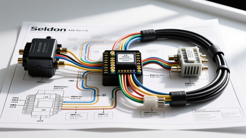
Seldon Auto Electric V8 Harness Wiring Diagram Walkthrough
Upgrading a classic or custom V8 platform with modern high-output charging and starting systems requires more than just swapping components; it demands a robust, properly engineered electrical architecture. The Seldon Auto Electric universal V8 conversion harness is widely regarded in the resto-mod and hot-rodding community for its heavy-duty gauge sizing, sealed connectors, and logical circuit routing. Whether you are running a 140-amp CS130-style alternator or a modern high-torque gear-reduction starter, understanding the exact wiring diagram is critical to preventing voltage drop, alternator diode failure, and parasitic draws.
This comprehensive walkthrough dissects the Seldon Auto Electric V8 harness schematic, detailing the main power distribution, alternator excitation circuits, starter solenoid routing, and chassis grounding protocols. By following these specifications, you will ensure your vehicle’s electrical system meets SAE J1128 Low Tension Cable Standards for under-hood thermal and chemical resistance.
System Architecture and Main Power Distribution
The core of the Seldon Auto Electric harness relies on a centralized power distribution topology rather than the outdated daisy-chain methods found in 1970s factory harnesses. The main battery positive feed originates at the starter motor B+ terminal, utilizing a 4 AWG stranded copper cable (Seldon Part #SE-4AWG-RED) insulated with high-temp cross-linked polyethylene (SXL). This SXL insulation is rated for continuous operation at 125°C (257°F), which is essential when routing near ceramic-coated exhaust headers.
From the starter B+, the 4 AWG cable routes to a Seldon 150-amp ANL inline fuse block mounted on the firewall or inner fender. From the fuse block, the power splits:
- Main Feed to Alternator: A secondary 4 AWG red SXL wire runs directly to the alternator B+ output terminal. This ensures the alternator can push its full 140+ amp output back to the battery without bottlenecking through the starter solenoid.
- Cabin Power Feed: A 10 AWG red wire routes through the firewall grommet to the ignition switch and main cabin fuse panel, protected by a 40-amp MIDI fuse.
- Accessory Relays: Two 12 AWG feeds supply the headlight and fuel pump relay coils, ensuring high-draw accessories do not pull current through the ignition switch.
Alternator Excitation and Sense Circuit (CS-Series Walkthrough)
The Seldon harness is pre-configured for General Motors CS130 and CS144 internally regulated alternators, which utilize a specific 4-pin rectangular Weather-Pack connector. Miswiring this pigtail is the most common cause of overcharging or complete failure to excite the rotor field. According to AA1Car Alternator Diagnostics, the internal voltage regulator requires specific resistance and voltage thresholds on the 'L' and 'S' terminals to begin charging.
Below is the exact pinout and wire color code for the Seldon Auto Electric alternator pigtail:
| Terminal | Function | Seldon Wire Color | AWG | Routing / Connection Destination |
|---|---|---|---|---|
| L | Lamp / Excitation | White | 18 | Routes to dash warning lamp. Must include a 56-ohm inline resistor if using an LED bulb to provide initial rotor excitation current. |
| F | Field / PWM | Gray | 18 | Pulse Width Modulation signal. In standalone V8 swaps without a PCM, this wire is capped and sealed. Do not ground this wire. |
| P | Phase / Stator | Yellow | 18 | Outputs a square-wave AC voltage signal proportional to engine RPM. Routes to the electronic tachometer signal input. |
| S | Voltage Sense | Red | 10 | CRITICAL: Must connect directly to the battery positive terminal or the main distribution block. Do not splice this to the alternator B+ post, or the regulator will overcharge the battery to compensate for wire voltage drop. |
Starter Solenoid and High-Amp Trigger Routing
Modern V8 gear-reduction starters require a clean, high-amperage trigger signal to engage the solenoid without dropping the ignition coil voltage. The Seldon Auto Electric harness solves this by integrating a heavy-duty 30-amp Bosch-style relay into the starter trigger circuit.
When the ignition key is turned to 'START', a 14 AWG yellow/white tracer wire sends a 12V+ signal from the ignition switch to the relay coil (Terminal 86). Terminal 85 is grounded to the engine block. The relay then switches battery power from Terminal 30 (fed by a dedicated 10 AWG fused line from the battery) to Terminal 87, which sends a robust, clean 12V+ signal via a 12 AWG purple wire directly to the starter solenoid 'S' terminal. This prevents the infamous 'hot-start' issue where voltage drop across a long, aging ignition switch wire fails to pull the heavy starter solenoid plunger.
Chassis Bonding and Grounding Protocols
A wiring diagram is only half the equation; the return path (ground) dictates the success of the system. The Seldon Auto Electric kit includes three dedicated ground cables that must be installed precisely to avoid alternator whine in the audio system and erratic ECU sensor readings.
- Engine Block to Chassis (Main Ground): A 2 AWG bare copper braided strap. One end is bolted to the rear of the passenger side cylinder head (using a 3/8-16 bolt torqued to 35 lb-ft), and the other to a dedicated chassis tab. Both surfaces must be stripped to bare metal and coated with NO-OX-ID A-Special anti-oxidant paste to prevent galvanic corrosion.
- Engine Block to Battery Negative: A 4 AWG black SXL wire with heavy-duty closed-end ring terminals, crimped using a hydraulic press (never solder-only, as solder flows under high-vibration, high-heat starter cranking loads).
- Alternator Case Ground: While the alternator grounds through its mounting bracket, Seldon recommends an auxiliary 10 AWG black wire from the alternator rear housing bolt to the engine block to ensure the internal voltage regulator has a zero-resistance ground reference.
Real-World Troubleshooting and Voltage Drop Testing
Even with a flawless Seldon Auto Electric wiring diagram walkthrough, real-world installation variables can introduce faults. If your vehicle exhibits dimming headlights at idle or a battery that slowly dies over three days, perform these specific diagnostic tests:
1. The Alternator Sense Wire Voltage Drop Test
Set your digital multimeter (DMM) to DC Volts. Place the black probe on the battery negative terminal and the red probe on the alternator 'S' terminal wire (back-probing the Weather-Pack connector). With the engine running at 2,000 RPM and the headlights on, you should read within 0.1V of the actual battery post voltage. If the battery reads 14.2V but the 'S' terminal reads 13.4V, you have a 0.8V drop in the sense circuit. The regulator will compensate by pushing the alternator to 15.0V+, boiling your battery. Fix this by re-routing the Red 10 AWG sense wire directly to the battery positive post.
2. Starter Solenoid Parasitic Draw Isolation
If the vehicle has a parasitic draw exceeding the acceptable 50mA threshold, isolate the Seldon starter relay. Pull the 30-amp mini-fuse powering Terminal 30 of the starter relay. If the draw drops to normal, inspect the 12 AWG purple trigger wire. A common failure mode is the purple wire chafing against the exhaust header shield, creating a high-resistance short to ground that keeps the starter solenoid partially engaged or drains the battery through the relay coil.
3. Crimp and Termination Inspection
Inspect all Seldon ring terminals at the starter B+ and alternator B+. A loose crimp will cause localized heating. Use an infrared thermometer after a 15-minute drive; any terminal reading 40°F (22°C) hotter than ambient air temperature requires immediate re-crimping and the application of 3/8-inch adhesive-lined marine heat shrink to seal out moisture and prevent copper oxidation.
By strictly adhering to this Seldon Auto Electric wiring diagram walkthrough, utilizing the correct AWG sizing, and respecting the specific pinout requirements of modern internally regulated alternators, you will build a V8 electrical system that is reliable, efficient, and capable of supporting modern EFI and high-draw accessory loads.