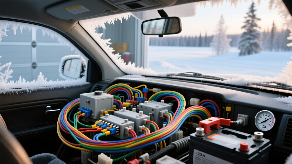
The Sub-Zero Electrical Environment
When dealing with automotive electrical systems in extreme climates, standard repair manuals often fall short. The principles applied by an auto electric Anchorage Alaska specialist are rooted in the harsh realities of sub-zero thermodynamics. In environments where winter temperatures routinely plunge below -20°F, electrical resistance behaves unpredictably, battery chemistry slows to a crawl, and standard wire insulation can shatter like glass. For beginners and DIY mechanics, understanding these cold-weather fundamentals is the difference between a reliable daily driver and a stranded vehicle on the Glenn Highway.
This guide breaks down the core electrical concepts required to survive extreme cold, from Cold Cranking Amps (CCA) math to sub-zero voltage drop testing and proper block heater circuit wiring.
Battery Chemistry and the CCA Math
The heart of any automotive starting system is the lead-acid battery. However, temperature dictates its actual output. According to the Battery Council International (BCI), Cold Cranking Amps (CCA) is defined as the number of amps a 12-volt battery can deliver at 0°F for 30 seconds while maintaining at least 7.2 volts. But what happens when the temperature drops to -20°F or -30°F?
As temperatures plummet, the sulfuric acid and water electrolyte mixture becomes more viscous, slowing the chemical reaction required to generate electrons. Simultaneously, engine oil thickens exponentially, increasing the mechanical load on the starter motor.
| Ambient Temp (°F) | Battery Capacity Available | Engine Oil Viscosity (5W-30) | Starter Amperage Draw |
|---|---|---|---|
| 80°F | 100% | Normal Flow | 120A - 150A |
| 32°F | 85% | Slight Thickening | 160A - 180A |
| 0°F | 70% | Heavy Resistance | 200A - 250A |
| -20°F | 50% | Severe Drag | 280A - 350A+ |
Beginner Takeaway: If your vehicle requires 250A to crank a cold, stiff engine at -20°F, but your battery only provides 50% of its rated 800 CCA (yielding just 400A), you are operating on a razor-thin margin. Any parasitic draw or corroded terminal will result in a no-crank condition. Always size your battery 20% above the manufacturer's minimum CCA requirement if you live in extreme northern climates.
Wire Insulation Standards: PVC vs. XLPE
A frequently overlooked aspect of cold-weather auto electrics is wire insulation. Standard aftermarket wiring often uses Polyvinyl Chloride (PVC) insulation. While PVC is flexible and cheap, it becomes brittle at approximately -40°F. The constant vibration of a running engine, combined with wind-chill factors on the highway, will cause PVC insulation to crack, exposing bare copper to road salt and moisture, leading to rapid galvanic corrosion.
Professional auto electricians in Alaska rely on wires that meet SAE J1128 specifications, specifically Cross-Linked Polyethylene (XLPE). Wires designated as GXL, SXL, or TXL feature XLPE insulation, which remains flexible down to -51°C (-60°F) and offers superior resistance to thermal shock and abrasion.
Wire Sizing for Extreme Cold Battery Cables
Cold weather increases the resistance of copper. To compensate for voltage drop over long cable runs in large trucks or SUVs, you must increase the AWG (American Wire Gauge) size. Never use the absolute minimum AWG in sub-zero climates.
- 4 AWG: Suitable for up to 150A (Small 4-cylinder engines, mild climates).
- 2 AWG: Suitable for up to 200A (Standard V6/V8 engines, recommended for 0°F to -20°F).
- 1/0 AWG: Suitable for up to 300A+ (Heavy-duty diesels, extreme cold cranking).
Block Heater and Timer Relay Circuits
Engine block heaters are mandatory for survival in Anchorage. A standard 120V AC frost plug heater draws between 300W and 750W. However, leaving them plugged in 24/7 wastes electricity and degrades the heating element. Most setups utilize a 120V timer or a 12V DC relay system to manage the AC load.
When wiring a heavy-duty 12V automotive relay to control a block heater contactor, you must use the correct ISO mini-relay pinout and wire gauges to prevent melting the harness:
- Pin 30 (12V B+ Feed): 10 AWG Red wire, fused at 30A near the battery.
- Pin 87 (Relay Output): 12 AWG Yellow/Purple wire to the timer/contactor coil.
- Pin 85 (Ground): 14 AWG Black wire to a clean chassis ground.
- Pin 86 (Ignition/Trigger): 16 AWG Brown/White wire from a switched 12V source or thermostat switch.
Note: On the 120V AC side of the contactor, never use standard automotive wire. Use 14 AWG or 12 AWG stranded copper building wire (THHN/THWN) rated for wet locations and extreme cold, housed in a liquid-tight flexible metal conduit to protect against road debris and ice impacts.
Cold-Weather Voltage Drop Diagnostics
When an auto electric Anchorage Alaska shop diagnoses a slow-crank issue, they do not just test the battery; they perform a voltage drop test on the starter circuit. Thermal contraction in freezing weather causes metal terminals to shrink slightly, breaking the seal on crimped connections and introducing micro-gaps that spike electrical resistance.
Step-by-Step Starter Circuit Voltage Drop Test
Set your digital multimeter (DMM) to DC Volts. You are measuring the difference in potential between two points while the circuit is under load (cranking).
- Positive Side Test: Place the red probe on the battery positive post (not the clamp) and the black probe on the starter motor B+ stud. Crank the engine. A reading above 0.5V indicates excessive resistance in the positive cable, fuse block, or isolation switch.
- Ground Side Test: Place the red probe on the starter motor casing (bare metal) and the black probe on the battery negative post. Crank the engine. A reading above 0.1V indicates a poor engine block ground or corroded battery negative clamp.
- Solenoid Trigger Test: Back-probe the starter solenoid 'S' terminal (usually a 16 AWG Yellow/Red wire) with the red probe, and ground the black probe. During cranking, voltage must not drop below 10.5V. If it does, the ignition switch or neutral safety switch contacts are failing in the cold.
Alternator Thermal Shock and Diode Failure
Alternators in extreme climates suffer from severe thermal cycling. An alternator casing can sit at -20°F overnight, then rapidly heat to over 200°F within 15 minutes of driving. This extreme expansion and contraction frequently cracks the solder joints on the internal voltage regulator and the rectifier bridge diodes.
If you experience dimming headlights at idle that brighten when revving the engine in the dead of winter, suspect a failing diode trio. To verify, check the AC voltage ripple at the battery terminals with the engine running and all accessories on. A healthy alternator should produce less than 50mV AC. If your DMM reads over 100mV AC, the rectifier is failing, and the alternator must be rebuilt or replaced with a unit featuring high-temp epoxy-sealed diodes.
Summary: Preparing for the Deep Freeze
Surviving winter requires respecting the physics of electricity in the cold. By upgrading to SAE J1128 XLPE wiring, properly sizing your battery cables to 2 AWG or 1/0 AWG, and rigorously performing voltage drop tests to eliminate thermal contraction resistance, you can build an electrical system that ignores the thermometer. Whether you are performing these upgrades in your own heated garage or seeking out a specialized auto electric Anchorage Alaska professional, these fundamentals remain the bedrock of cold-weather reliability.