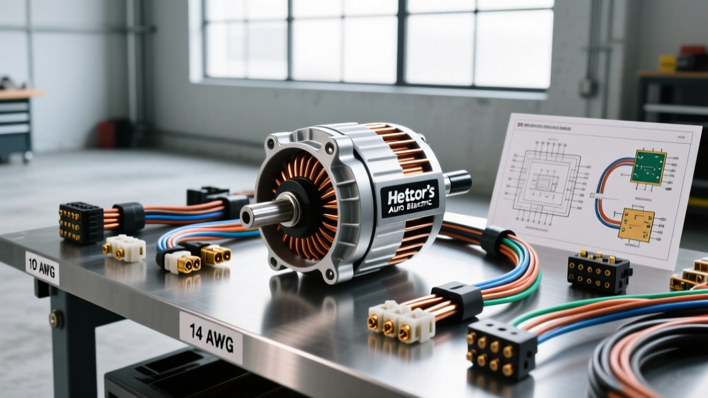
Evaluating Hector's Auto Electric High-Output Systems
When outfitting a vehicle for extreme electrical loads—such as off-road lighting arrays, heavy-duty winches, or competition-level mobile audio—the factory charging system quickly becomes the limiting factor. Hector's Auto Electric has established a benchmark in the aftermarket sector by engineering high-output alternators and complementary heavy-duty wiring harnesses designed to sustain continuous high-amperage draws without thermal degradation. This guide compares Hector's Auto Electric Pro-Series components against standard Original Equipment Manufacturer (OEM) setups, providing the technical specifications, wire gauge requirements, and pinout configurations necessary for a reliable, high-amp electrical architecture.
Product Comparison: Hector's Pro-Series vs. Standard OEM
The fundamental difference between a standard 130A OEM alternator and a Hector's Auto Electric 220A Pro-Series unit lies in the internal electromagnetic architecture and thermal management. OEM alternators are designed for peak efficiency at highway RPMs to meet basic factory parasitic loads (ECU, fuel pump, HVAC, lighting). They typically utilize round-wire stators which suffer from higher electrical resistance and lower slot-fill factors.
Stator Winding and Thermal Architecture
Hector's Auto Electric utilizes a flat-wire 'hairpin' stator design. This increases the copper slot-fill density by up to 20% compared to OEM round-wire stators, significantly lowering internal resistance (I²R losses) and reducing heat generation at high amperages. Furthermore, while OEM stators typically rely on Class F insulation (rated to 155°C / 311°F), Hector's Pro-Series employs Class H enamel insulation rated to 180°C (356°F). This thermal headroom is critical when the alternator is mounted low in the engine bay near exhaust manifolds, where ambient under-hood temperatures frequently exceed 120°C during sustained idling.
Additionally, the rectifier assembly in Hector's units utilizes avalanche-rated 50A diodes. In the event of a sudden load dump (such as a winch solenoid disengaging or a battery cable snapping), these diodes safely absorb the inductive voltage spikes, preventing the catastrophic regulator failure commonly seen in OEM units equipped with standard 25A diodes.
Wiring Harness Upgrades: AWG and Insulation Specs
Upgrading to a 220A alternator without upgrading the wiring harness is a severe fire hazard. According to SAE J1128 standards for low-tension primary cable, wire gauge selection must account for both continuous current and voltage drop over the length of the run. The factory B+ charging wire is typically 8 AWG or 6 AWG, which is rated for a maximum continuous load of roughly 60A to 80A in high-temperature engine bay environments.
B+ Cable and Grounding Architecture
For Hector's Auto Electric 220A and 270A kits, the B+ output terminal must be wired directly to the primary battery positive post using a minimum of 2 AWG TXL (Thin-Wall Cross-Linked) copper wire. TXL insulation is superior to standard PVC, offering higher abrasion resistance and a tighter bend radius, which is essential for routing through crowded engine bays. For runs exceeding 8 feet, or for 300A+ applications, 1/0 AWG fine-strand welding cable is mandatory to keep voltage drop below 0.2V.
Protection at the battery terminal requires a 300A Mega Fuse (or ANL fuse) mounted within 7 inches of the battery post. On the grounding side, the factory engine-to-chassis ground straps are rarely sufficient for high-amp returns. You must install a supplemental 2 AWG braided copper ground strap from the alternator casing directly to the engine block, and a secondary 1/0 AWG strap from the engine block to the vehicle chassis near the battery negative terminal.
Hector's Auto Electric Regulator Pinout & Connector Guide
Proper voltage regulation requires accurate feedback from the battery. Hector's Auto Electric external and pigtail-regulated units utilize a 4-pin Delphi Connection Systems Metri-Pack 280 series connector. Miswiring this connector is the leading cause of overcharging and undercharging in aftermarket installations.
- Pin 1 (L-Terminal / Lamp): Red/White wire, 18 AWG. Connects to the ignition-switched 12V source via the dash charge indicator lamp. This provides the initial 'excitation' current to the rotor to begin the charging process.
- Pin 2 (S-Terminal / Sense): Orange wire, 14 AWG. This is the most critical wire. It must be routed directly to the positive battery post (or the main distribution block). It draws near-zero current but provides the regulator with true battery voltage. If connected to the alternator B+ terminal, voltage drop in the main cable will cause the regulator to overcharge the battery.
- Pin 3 (I-Terminal / Ignition): Pink wire, 18 AWG. Connects to a keyed 12V ignition source. This wakes up the regulator's internal logic board when the vehicle is turned on.
- Pin 4 (G-Terminal / Ground): Black wire, 14 AWG. Must be terminated to a clean, bare-metal point on the alternator casing or engine block, not a painted chassis surface.
Technical Specification & Selection Chart
| System Load Profile | Hector's Alternator Model | Peak Output (Amps) | Idle Output (Amps) | Required B+ Wire (AWG) | Main Fuse Rating |
|---|---|---|---|---|---|
| Standard Daily / Light Audio | HE-140 OEM-Style | 140A | 85A @ 800 RPM | 6 AWG TXL | 175A Mega |
| Off-Road / Winch / LED Arrays | HE-220 Pro-Series | 220A | 150A @ 800 RPM | 2 AWG TXL | 250A Mega |
| Competition Audio / Hydraulics | HE-320 Hairpin Elite | 320A | 210A @ 900 RPM | 1/0 AWG Welding | 350A ANL |
Installation Best Practices & Torque Specs
Heavy-duty alternators place significant lateral loads on the mounting brackets and drive belts. When installing Hector's Auto Electric units, adhere to the following mechanical specifications:
- B+ Terminal Nut: The M8 stud on the rear output terminal requires exactly 12-15 Nm (8.8-11 lb-ft) of torque. Overtightening will crack the internal rectifier block; undertightening causes micro-arcing and terminal melting.
- Crimp Terminations: Do not use solder for high-amp B+ connections. Solder has a lower melting point and becomes brittle under engine vibration. Use a hydraulic crimping tool with closed-barrel copper lugs, followed by 3:1 ratio adhesive-lined heat shrink to seal out moisture and prevent copper oxidation.
- Belt Tension: High-output units require increased rotational force. Upgrade the factory serpentine belt to a high-grip aramid-reinforced belt (e.g., Gates FleetRunner). Tension should be set to allow exactly 1/2 inch of deflection at the longest span of the belt under 10 lbs of thumb pressure.
Troubleshooting & Real-World Failure Modes
Even with premium components like those from Hector's Auto Electric, installation errors can lead to system failure. Refer to this diagnostic matrix when troubleshooting high-amp charging systems.
Symptom: Battery Voltage Drops to 12.2V at Idle with Lights On
Cause: Pulley ratio mismatch or excessive voltage drop on the Sense (S) wire. If the alternator pulley is too large, the rotor will not reach the minimum 2,200 RPM required to achieve peak magnetic saturation at engine idle. Alternatively, if the Pin 2 Sense wire is reading voltage drop due to a poor crimp, the regulator falsely believes the battery is fully charged and dials back the field current.
Fix: Verify alternator shaft RPM using an optical tachometer. Perform a voltage drop test on the Sense wire (should be < 0.05V).
Symptom: Alternator Case is Too Hot to Touch (Exceeding 200°F)
Cause: Inadequate grounding or continuous max-amperage draw exceeding the unit's thermal duty cycle. If the engine block ground is corroded, the alternator attempts to ground through the smaller mounting bolts, generating massive resistance heat. Furthermore, heavy-duty alternators are typically rated for a 70% continuous duty cycle; running a 220A alternator at a dead-short 220A draw for hours will overwhelm the internal cooling fan.
Fix: Clean the engine block ground mating surface to bare metal with a wire wheel. Install the supplemental 2 AWG ground strap. For continuous 100% duty cycle applications, upgrade to a liquid-cooled alternator or add a dedicated 12V blower fan ducting ambient air to the alternator's rear ventilation louvers.
For further engineering benchmarks on heavy-duty charging systems, refer to the testing methodologies outlined in SAE J56, which defines the rigorous thermal and electrical shock testing required for commercial-grade automotive alternators. Upgrading to Hector's Auto Electric components is an exercise in applied electrical engineering; respecting the AWG limits, pinout logic, and thermal boundaries ensures a charging system that will outlast the vehicle itself.