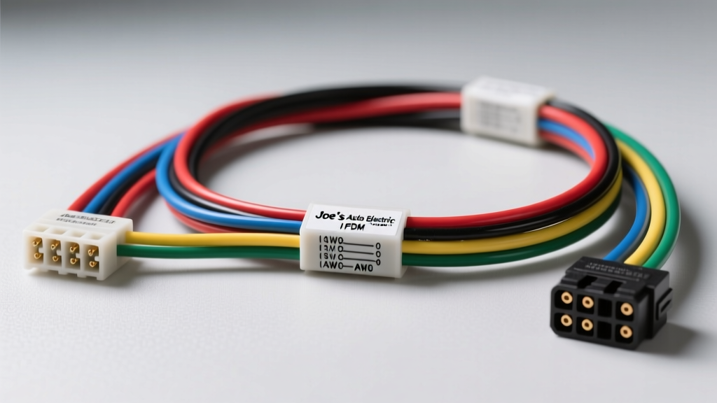
Introduction to the Joe's Auto Electric II Harness Architecture
When upgrading a legacy vehicle, building a restomod, or wiring a custom off-road rig, traditional glass-tube fuse blocks and mechanical relay forests often fall short of modern reliability standards. The Joe's Auto Electric II universal wiring system represents a shift toward solid-state Power Distribution Modules (PDM) integrated with high-density bulkhead connectors. This technical reference provides the exact wire color codes, American Wire Gauge (AWG) specifications, pinout configurations, and relay logic required to properly install and troubleshoot the Joe's Auto Electric II harness system.
Unlike legacy harnesses that rely on dozens of individual blade fuses and ISO mini relays, the Joe's Auto Electric II architecture utilizes a centralized, sealed PDM. This module uses solid-state switches and electronic circuit breakers to manage high-current loads, drastically reducing voltage drop and eliminating the risk of corroded mechanical relay contacts. Below is the comprehensive specification guide for integrators and master technicians.
Core System Specifications and SAE Standards
All primary wiring in the Joe's Auto Electric II kit adheres strictly to SAE J1128 standards for low-tension primary cable. The wire insulation is cross-linked polyethylene (XLPE), rated for continuous operation at 125°C, which provides superior resistance to under-hood heat soak compared to standard PVC insulation. The copper stranding is fine-wire (Type SGT/SXL), ensuring high flexibility and resistance to vibration-induced fatigue.
Wire Gauge and Color Code Reference Chart
Proper circuit protection relies on matching the AWG size to the electronic breaker threshold inside the PDM. The following table outlines the factory pre-terminated circuits, their designated wire colors, and maximum continuous load ratings.
| Circuit Function | AWG Size | Wire Color Code | PDM Breaker Rating | Max Continuous Load |
|---|---|---|---|---|
| Starter Solenoid Trigger | 12 AWG | Red w/ White Stripe | 15A | 10A |
| Primary Cooling Fan | 10 AWG | Blue | 30A | 25A |
| Secondary Cooling Fan | 10 AWG | Blue w/ Black Stripe | 30A | 25A |
| Headlights (High Beam) | 12 AWG | Yellow | 20A | 15A |
| Headlights (Low Beam) | 12 AWG | Yellow w/ Red Stripe | 20A | 15A |
| ECU Main Power Relay | 14 AWG | Green | 15A | 10A |
| Fuel Pump Prime/Run | 12 AWG | Purple | 20A | 15A |
| Dash Illumination | 18 AWG | Orange | 5A | 3A |
| Horn Output | 14 AWG | Dark Green | 15A | 12A |
32-Pin AMP Superseal Bulkhead Pinout
The firewall transition is handled by a sealed 32-pin AMP Superseal connector, eliminating the need for individual rubber grommets and preventing moisture ingress into the cabin. When diagnosing cabin-to-engine bay communication faults, verifying the pinout at this bulkhead is the critical first step. The connector uses TE Connectivity Superseal 1.5 series terminals, requiring a specific ratcheting crimp tool (e.g., TE CERTI-CRIMP) to ensure proper wire barrel compression and insulation grip.
Engine Bay Side (Male Connector) Pin Assignments
- Pin 1: Battery + Feed (8 AWG, Red) - Direct from alternator output stud.
- Pin 2: Main Chassis Ground (8 AWG, Black) - Must terminate to clean, bare metal on the cylinder head or intake manifold.
- Pin 3: Ignition Switched 12V (14 AWG, Pink) - Sourced from the ignition switch 'RUN/START' terminal.
- Pin 4: Accessory 12V (14 AWG, Purple) - Sourced from the ignition switch 'ACC' terminal.
- Pin 5: Crank Signal (18 AWG, Yellow/Black) - Low-side trigger for starter solenoid.
- Pin 6: Cooling Fan Temp Switch Ground (18 AWG, Black/White) - Routes to the thermostat housing thermal switch.
- Pin 12: High Beam Trigger (18 AWG, Light Green) - Routes from the steering column dimmer switch.
- Pin 15: CAN-H (20 AWG, Twisted Pair w/ Pin 16) - Reserved for ECU telemetry and digital dash integration.
- Pin 16: CAN-L (20 AWG, Twisted Pair w/ Pin 15) - Must maintain 120-ohm termination resistance at the ECU.
Relay Integration and Low-Side Trigger Logic
While the PDM handles most medium-current loads internally, the Joe's Auto Electric II system retains provisions for external ISO mini relays for ultra-high inrush current devices, such as heavy-duty off-road lighting arrays or nitrous oxide solenoid heaters. Understanding the trigger logic is essential for preventing back-EMF damage to the PDM's solid-state switches.
The PDM outputs designated for relay triggers are low-side (ground) switches. This means the PDM provides the ground path to complete the relay coil circuit (Pin 85), while Pin 86 of the relay coil must be wired to a constant or switched 12V source. Always install a flyback diode across the relay coil (cathode to 12V, anode to PDM trigger) or use an ISO relay with an integrated suppression resistor to prevent inductive voltage spikes from exceeding the PDM's 40V clamping threshold.
Crimping and Termination Best Practices
According to Littelfuse PDM design guidelines, over 70% of automotive electrical failures originate at the termination point, not the wire itself. The Joe's Auto Electric II harness utilizes open-barrel F-crimps for all bulkhead and sensor connections. To achieve a gas-tight seal that prevents oxidation:
- Strip the XLPE insulation using precision wire strippers to avoid nicking the copper strands. A single nicked strand can reduce the tensile strength and current-carrying capacity of an 18 AWG wire by up to 20%.
- Use a ratcheting crimp tool calibrated for the specific terminal series. The crimp must pass the 'pull test' (minimum 25 lbs of force for 18 AWG) without the wire slipping.
- Seal all exposed barrel crimps using dual-wall polyolefin heat shrink with an inner adhesive lining. The adhesive must melt and flow out of the ends of the shrink tube to ensure complete moisture encapsulation.
Troubleshooting Voltage Drop and PDM Faults
Because the Joe's Auto Electric II system replaces traditional fuses with electronic breakers, diagnosing a tripped circuit requires a digital multimeter (DMM) rather than a visual inspection. Follow this decision tree for PDM-related faults:
Symptom: Circuit Intermittently Shuts Off Under Load
- Step 1: Perform a voltage drop test on the power side. Place the DMM positive lead on the battery positive post and the negative lead on the load side of the component. With the circuit active, a reading greater than 0.20V indicates excessive resistance (corroded bulkhead pin or failing component ground).
- Step 2: Perform a voltage drop test on the ground side. Place the DMM positive lead on the component chassis and the negative lead on the battery negative post. A reading greater than 0.10V indicates a poor chassis ground.
- Step 3: If voltage drops are within spec, measure the amperage draw of the component using an inductive clamp meter. If the draw exceeds the PDM breaker rating (e.g., a cooling fan drawing 32A on a 30A circuit), the PDM is correctly tripping to prevent a thermal event. The mechanical fault lies within the component's motor or binding bearings.
Symptom: PDM Channel Will Not Activate via Switch
- Step 1: Verify the low-side trigger signal. Back-probe the switch input wire at the PDM connector. When the switch is actuated, the DMM should read less than 0.5V (ground). If it reads 12V, the cabin switch or wiring is open.
- Step 2: Check for thermal shutdown. The Joe's Auto Electric II PDM features an internal heat sink. If the module casing exceeds 85°C, it will derate or shut down channels to protect the MOSFETs. Ensure the PDM is mounted in an area with adequate airflow, away from exhaust headers or radiator heat soak.
By adhering to these technical specifications, wire color codes, and diagnostic procedures, technicians can ensure the Joe's Auto Electric II harness delivers reliable, maintenance-free power distribution for the life of the vehicle.