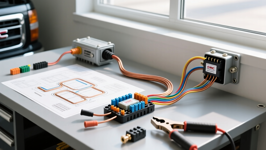
Upgrading the GMC Sierra Auto Electric Architecture
When outfitting a GMC Sierra for heavy-duty work, overlanding, or commercial snow plowing, the factory electrical system quickly reaches its limits. The OEM under-hood fuse block on both the GMT800 (1999-2006) and K2XX (2014-2018) platforms is densely packed and often lacks the spare high-amperage circuits required for modern high-draw accessories. Performing a comprehensive Sierra auto electric upgrade by installing a high-current auxiliary fuse block and reinforcing the main charging wires is essential for reliable, safe operation.
In this practical how-to guide, we will walk through the installation of a 6-circuit auxiliary fuse block, upgrading the main battery feed with 1/0 AWG SGX cable, and properly integrating the alternator sense circuits to prevent the Powertrain Control Module (PCM) from misreading system voltage.
Tools and Materials Required
Before beginning any Sierra auto electric modification, gather the correct automotive-grade materials. Never use household stranded wire or copper-clad aluminum (CCA) wire under the hood. According to the SAE J1128 Low Tension Cable Standard, under-hood wiring must withstand high temperatures and chemical exposure.
- Main Feed Wire: 1/0 AWG SGX (Cross-linked polyethylene) battery cable, Red.
- Secondary Wire: 10 AWG TXL primary wire (Blue for alternator sense, Black for grounds).
- Overcurrent Protection: 150A ANL fuse and weatherproof holder.
- Distribution: 6-circuit auxiliary fuse block with stud-type main input (e.g., Blue Sea Systems ST).
- Terminals: 3/8-inch tinned copper ring terminals with adhesive-lined heat shrink (3M MDT, 3:1 shrink ratio).
- Tools: Hex-profile wire crimper (minimum 1/0 AWG capacity), wire strippers, heat gun, torque wrench, digital multimeter (DMM).
Step-by-Step Auxiliary Fuse Block Installation
Step 1: Battery Disconnect and Routing the Main Feed
Always disconnect the negative battery terminal first. On the GMT800 Sierra, the negative cable attaches to the engine block and the passenger-side frame rail. Remove the negative cable and isolate it with a non-conductive boot.
Measure the distance from the positive battery terminal to your desired auxiliary fuse block location (typically on the driver-side inner fender, near the OEM airbox). Cut the 1/0 AWG SGX red cable, adding 12 inches for routing slack. Route the cable along the inner fender liner, strictly avoiding the exhaust manifolds and steering shaft. Secure the wire every 8 inches using UV-resistant nylon zip ties and split-loom tubing where the wire passes near sharp metal brackets.
Step 2: Terminating and Fusing the 1/0 AWG Main Power
Strip 5/8-inch of insulation from the 1/0 AWG cable. Slide a piece of 3M MDT adhesive-lined heat shrink onto the wire before crimping. Insert the bare copper into the 3/8-inch tinned ring terminal. Using a hex-profile crimper, apply a full hexagonal crimp. The adhesive-lined heat shrink must be applied over the barrel and the wire insulation. When heated, the inner adhesive melts and seals out moisture, preventing the green corrosion common in poorly terminated Sierra auto electric systems.
Install the 150A ANL fuse holder on the main feed. Per GM Upfitter Integration Guidelines, overcurrent protection must be installed within 12 inches of the power source. Mount the fuse holder securely to the firewall or inner fender, ensuring the positive terminal connects directly to the battery positive post or an approved OEM power distribution stud.
Step 3: Grounding the Auxiliary Block
An auxiliary fuse block is only as good as its ground. Do not rely on sheet metal screws into the inner fender. Locate a factory body-to-frame ground bolt, or drill a 3/8-inch hole into the frame rail. Clean the metal down to bare, shiny steel using a wire wheel. Attach a 1/0 AWG black ground wire from the fuse block's negative bus bar to this clean frame point. Coat the connection in dielectric grease after torquing the bolt to 25 ft-lbs to prevent rust creep.
GMC Sierra Auxiliary Circuit Allocation Chart
Properly sizing the branch circuit wires and fuses is critical. The table below outlines a standard configuration for a Sierra off-road or plow-prep build.
| Circuit | Accessory Application | Fuse Rating | Wire Gauge (TXL) | Wire Color Code |
|---|---|---|---|---|
| C1 | Winch Contactor Relay Coil | 30A | 8 AWG | Red |
| C2 | LED Light Bar (30-inch) | 20A | 12 AWG | Yellow |
| C3 | Onboard Air Compressor | 40A | 10 AWG | Blue |
| C4 | CB Radio / Telematics | 15A | 14 AWG | Green |
| C5 | Auxiliary Heated Mirrors/Seats | 20A | 12 AWG | Purple |
| C6 | Spare / Future Expansion | Blank | N/A | N/A |
Alternator Sense and PCM Integration (GMT800 AD244)
If your Sierra utilizes the common AD244 4-pin alternator connector, understanding the PCM's voltage regulation strategy is vital. The 4-pin connector features L (Lamp), S (Sense), I (Ignition), and F (Field) terminals. The 'S' terminal reads actual battery voltage to adjust the alternator's field current.
When adding high-draw accessories to your new auxiliary block, voltage drop between the alternator and the battery can cause the PCM to overcharge the battery, boiling the electrolyte. To fix this, run a dedicated 10 AWG Blue TXL sense wire from the battery positive terminal (on the load side of the main fuse) directly to the alternator 'S' pin cavity. This ensures the PCM reads true battery voltage, not the voltage at the alternator B+ post, which can be artificially elevated during heavy accessory loads.
The 'Big Three' Wiring Upgrade
To maximize the output of your Sierra's alternator, perform the 'Big Three' upgrade using 1/0 AWG SGX wire:
- Alternator Case to Chassis: Ensures the alternator has a dedicated ground path, bypassing potentially corroded engine mounts.
- Battery Negative to Chassis: Reinforces the main return path for all vehicle electronics.
- Engine Block to Chassis: Stabilizes the ground reference for the PCM and fuel injectors.
Torque all alternator and battery terminal connections to the manufacturer's specifications. According to Battery Council International (BCI) guidelines, side-post and top-post adapter nuts should generally be torqued to 10-12 ft-lbs to prevent thread stripping while ensuring maximum surface contact.
Troubleshooting Common Sierra Electrical Gremlins
After installation, perform a voltage drop test with the engine running and accessories loaded. Set your DMM to DC Volts. Place the red probe on the alternator B+ terminal and the black probe on the auxiliary fuse block main input stud. A healthy 1/0 AWG circuit should show a voltage drop of less than 0.2V. If you read 0.5V or higher, you have a poor crimp, a failing ANL fuse, or inadequate wire sizing.
Next, test the ground side. Place the red probe on the auxiliary fuse block ground bus and the black probe on the battery negative post. The drop should be less than 0.1V. High ground resistance in a Sierra auto electric system often manifests as flickering headlights, erratic fuel gauge readings, or delayed transmission shifting due to PCM voltage reference errors. By following these strict wiring protocols, your Sierra will handle extreme electrical loads with OEM-level reliability.