The High-Amp Charging System Dilemma: Specialist vs. Mass Market
When building overlanding rigs, competition audio vehicles, or heavy-duty towing setups, the factory 130A to 160A alternator quickly becomes the weakest link in the electrical architecture. Enthusiasts and fleet managers frequently weigh the merits of sourcing from a dedicated specialist like Kelly's Auto Electric against mass-market OEM replacements or big-box auto parts store remanufactured units. While a standard OEM replacement is sufficient for restoring a stock vehicle to factory specifications, it fundamentally lacks the thermal mass and diode capacity required for sustained 200A+ continuous loads. This product comparison and selection guide breaks down the engineering differences between specialist high-output builds and standard automotive electrical components, providing actionable wiring, pinout, and upgrade data for serious builds.
Core Component Comparison: Stator and Rotor Architecture
The heart of any alternator is the stator and rotor assembly. Mass-market remanufactured alternators typically reuse the original Lundell (claw-pole) rotor and standard round-wire stators. While cost-effective, these round-wire stators suffer from lower copper fill factors, resulting in higher resistance and excessive heat generation under heavy load.
Hairpin Stator Technology
Specialist suppliers like Kelly's Auto Electric utilize high-density hairpin stator windings for their 200A to 300A units. Hairpin technology uses rectangular copper wires that pack tightly into the stator slots, increasing the copper cross-section by up to 20% compared to round wire. This drastically reduces I²R (heat) losses. When selecting a high-amp unit, always verify the stator topology. A genuine high-output unit will also feature a custom-wound rotor with a higher number of turns to achieve full output at lower RPMs, ensuring your charging system keeps up at idle speeds where standard units typically drop below 40% of their rated capacity.
Rectifier Bridge and Avalanche Diodes
Standard OEM alternators use a basic 6-diode rectifier bridge. Under high-load conditions, particularly when dealing with the inductive kickback from heavy aftermarket accessories, these diodes are prone to thermal runaway. High-end specialist builds upgrade to a 12-diode or heavy-duty avalanche diode bridge. Avalanche diodes are specifically engineered to clamp transient voltage spikes (load dump events) that can exceed 80V when a battery cable is disconnected under load, protecting both the alternator and the vehicle's sensitive CAN-bus modules.
Wiring Infrastructure: Upgrading the Big Three
Installing a 220A alternator on a factory wiring harness is a guaranteed way to melt the firewall bulkhead connector or induce severe voltage drop. Upgrading the 'Big Three' wiring is mandatory. This involves replacing the Alternator B+ to Battery Positive, Battery Negative to Chassis, and Engine Block to Chassis cables. According to SAE J1141 standards for automotive wiring, selecting the correct AWG and insulation type is critical for under-hood environments.
| System Load (Amps) | Recommended AWG Size | Wire Type & Insulation | Max Run Length (ft) |
|---|---|---|---|
| Up to 150A | 2 AWG | SGT / PVC (105°C) | 8 ft |
| 150A - 220A | 1/0 AWG | SGT / XLPE (125°C) | 10 ft |
| 220A - 300A+ | 2/0 AWG | SGT / XLPE (125°C) | 12 ft |
Expert Selection Note: Avoid using standard copper welding cable for the Big Three upgrade. While welding cable is highly flexible, its standard EPDM or PVC jacket is not rated for the continuous 125°C under-hood temperatures or the chemical exposure (oil, transmission fluid, battery acid) found in an engine bay. Always specify SGT (Standard Ground Wire) or SXL (Cross-linked polyethylene) automotive primary cable. SXL insulation is significantly thinner and more heat-resistant, allowing for easier routing through tight engine bays while handling higher thermal loads.
Connector Selection and Terminal Crimping Standards
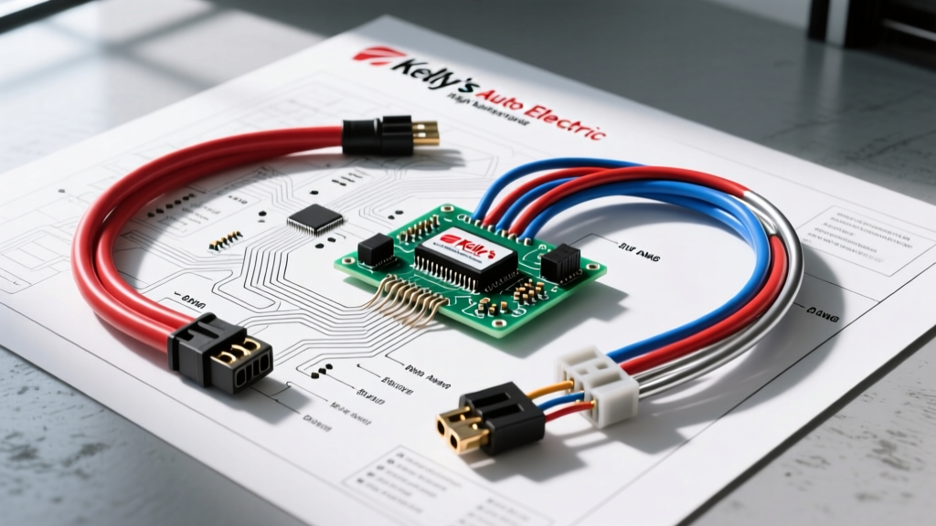
The transition from the alternator pigtail to the main chassis harness is a frequent failure point. Mass-market repair kits often rely on cheap, open-barrel spade connectors that vibrate loose and cause high-resistance arcing. When sourcing a custom harness from Kelly's Auto Electric or building your own, insist on sealed OEM-style connectors.
- Exciter/Sense Pigtails: Use AMP Superseal 1.5 or Metri-Pack 280 series connectors. These feature silicone ribbed seals that prevent moisture ingress.
- Auxiliary High-Amp Outputs: For secondary B+ posts used to feed winch solenoids or audio distribution blocks, utilize Deutsch DT series connectors or heavy-duty AMP CPC (Circular Plastic Connector) housings with machined solid contacts.
- Crimping Standards: Terminals must be crimped using a closed-barrel, ratcheting crimp tool. Per Delphi Aptiv connector specifications, a properly crimped Metri-Pack 280 terminal must withstand a minimum tensile pull-out force of 45 lbs without the wire slipping from the barrel.
Alternator Pinout Mapping and Voltage Sense Routing
Modern high-output alternators rely on precise PCM or internal regulator signaling to manage field coil excitation. The most common configuration on high-amp Japanese and domestic applications is the Denso-style 3-pin or 4-pin connector. Miswiring these pins will result in either zero output or immediate voltage regulator failure.
Denso 3-Pin Connector Pinout (L, S, IG)
- Pin L (Lamp / Exciter): Typically a 14 AWG White or Black/White wire. This provides the initial excitation current to the rotor. It must be connected to a switched 12V ignition source, often routed through a dash warning lamp or a PCM-controlled ground circuit.
- Pin S (Sense): Typically a 12 AWG Yellow or Red wire. Critical Routing Rule: This wire must be routed directly to the positive terminal of the main battery or the main distribution busbar. If you connect the Sense wire to the alternator's B+ output post, the regulator will read the alternator's voltage, not the battery's voltage. Under a 200A load, the voltage drop across the 1/0 AWG cable can be 0.5V or more. The regulator will compensate by over-exciting the field coil, pushing system voltage to 15.5V+ at the battery, causing severe overcharging and battery gassing.
- Pin IG (Ignition): Typically a 12 AWG Yellow wire. Tied to a fused ignition-on circuit to wake the internal voltage regulator.
Real-World Failure Modes and Diagnostic Insights
When troubleshooting a high-amp charging system installed via specialist components, technicians must look beyond basic multimeter voltage checks. A common failure mode in high-output systems is B+ Terminal Thermal Fatigue. The massive current flow generates heat at the M8 output stud. If the terminal nut is not torqued to the manufacturer's specification (typically 12 to 15 Nm for an M8 copper stud), microscopic arcing occurs. Over time, this oxidizes the copper terminal, increasing resistance and eventually melting the rear bearing housing. Always use a dedicated torque wrench on the alternator output nut, and never use standard steel washers; always use thick, plated copper or brass washers to maximize surface contact area and thermal conductivity.
Another frequent issue is PCM Field Wire Overloading. Some modern vehicles use the PCM to control the alternator's field coil via a PWM (Pulse Width Modulation) signal on the L or COM terminal. If an aftermarket high-amp regulator draws more than 500mA of excitation current, it can fry the PCM's internal driver transistor. When installing a Kelly's Auto Electric high-amp unit on a late-model CAN-bus vehicle, always verify the regulator's exciter draw. If it exceeds the factory PCM limit, you must install an intermediate 30A automotive relay to isolate the PCM from the alternator's high-current field circuit.
Final Selection Verdict
For standard daily drivers, an OEM-spec remanufactured alternator is the correct, cost-effective choice. However, for vehicles demanding sustained 200A+ output, the engineering superiority of specialist suppliers like Kelly's Auto Electric becomes undeniable. By combining hairpin stators, avalanche diode bridges, and pairing them with properly gauged SXL wiring and sealed Metri-Pack connectors, you create a charging infrastructure that is not only capable of handling extreme electrical loads but is fundamentally protected against the thermal and vibrational failure modes that plague mass-market upgrades.