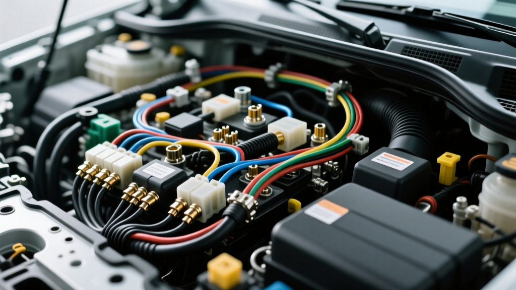
The Tech Center Auto Electric Standard
When master technicians and OEM engineers refer to tech center auto electric protocols, they are defining the rigorous, uncompromising standards required to maintain modern vehicle electrical architectures. Unlike home household wiring, automotive electrical systems operate in high-vibration, extreme-temperature, and moisture-heavy environments while managing sensitive ECU logic signals alongside high-amperage power distribution. Cutting corners in this environment does not just cause a blown fuse; it leads to catastrophic harness fires, destroyed powertrain control modules (PCMs), and fatal airbag deployment failures.
This guide outlines the critical safety warnings and most common wiring mistakes that separate professional-grade installations from dangerous DIY hacks.
Critical Safety Warnings Before Touching the Harness
SRS and Airbag Circuit Hazards
The Supplemental Restraint System (SRS) is the most dangerous circuit in any vehicle. SRS wiring is universally identified by yellow or bright orange corrugated looms and connectors. These circuits contain pyrotechnic squibs that deploy airbags and seatbelt pretensioners. Before performing any electrical work near the steering column, kick panels, or headliner, you must disconnect the negative battery terminal and wait a minimum of 15 to 30 minutes (refer to OEM service manuals, as some hybrid systems require up to 60 minutes for high-voltage capacitor discharge). Probing an active SRS wire with a standard digital multimeter (DMM) can output enough micro-current to inadvertently trigger the squib, causing severe injury.
High-Amperage Alternator Upgrade Protocols
Upgrading from a stock 80A alternator to a high-output 200A+ unit for off-road lighting or heavy winching requires more than just bolting on the new unit. The stock 6 AWG or 8 AWG main charge wire will melt under sustained 180A loads. A proper tech center auto electric upgrade mandates stepping up to 1/0 AWG pure copper welding cable. Furthermore, you must install a 250A ANL or Mega Fuse within 18 inches of the battery positive terminal to protect the new cable in the event of a short to ground.
Top 4 Common Wiring Mistakes (And How to Fix Them)
Mistake 1: Soldering Under-Hood Connections
A pervasive myth is that soldering wires creates the strongest bond. In automotive applications, solder wicks into the wire strands via capillary action, creating a rigid, inflexible joint. Under constant engine vibration, this rigid point becomes a stress riser, leading to copper fatigue and eventual wire breakage inside the insulation. According to TE Connectivity crimping best practices, open-barrel or closed-barrel mechanical crimps using ratcheting tools are the OEM standard. Crimping creates a cold-weld, gas-tight connection that maintains strand flexibility and resists vibration fatigue.
Mistake 2: Add-a-Circuit Fuse Tap Overloads
Piggyback fuse taps (Add-a-Circuit) are popular for powering dashcams or relays, but they are frequently misused. If you tap into a 10A circuit (like the wiper motor) to power a 10A accessory, the original 14 AWG feed wire from the fuse box is now carrying 20A. The 10A fuse protecting the feed wire will blow, but if a previous owner installed a 20A fuse, the 14 AWG wire will overheat and catch fire behind the dash. Always use a dedicated relay wired directly to the battery for accessories drawing more than 5A, using the fuse tap only to trigger the low-amperage relay coil.
Mistake 3: Daisy-Chaining Grounds and Painted Surfaces
Grounding to a painted bolt or stacking multiple ring terminals on a single stud increases circuit resistance. A high-resistance ground causes voltage drops, leading to dim headlights, erratic fuel pump operation, and ECU sensor faults. A proper ground requires sanding down to bare, shiny metal, using a star washer to bite through any micro-corrosion, and applying NO-OX-ID anti-oxidant grease. Always perform a voltage drop test: set your DMM to DC Volts, place the red probe on the component casing and the black probe on the battery negative terminal. Under load, a healthy ground will read less than 0.1V.
Mistake 4: Ignoring Relay Coil Kickback
When wiring a standard ISO mini relay (Pins 30, 87, 85, 86), technicians often forget the flyback diode. When the ECU or switch cuts power to the relay coil (Pins 85 and 86), the collapsing magnetic field generates a high-voltage reverse spike (inductive kickback) that can instantly destroy the delicate driver transistor inside the ECU. Always wire a 1N4004 diode in reverse bias across the coil pins to safely dissipate this spike.
Technical Reference: AWG Sizing & Amperage Chart
Adhering to SAE International J1128 standards for low-tension primary cable ensures your wire gauge matches the thermal limits of the circuit. The following chart assumes a standard 12V-14V system with a maximum 20-foot run (40-foot total round trip) and a 10% allowable voltage drop.
| AWG Size | Max Amps (Chassis) | Max Length (One Way) | Common Automotive Application |
|---|---|---|---|
| 18 AWG | 10A | 20 ft | ECU Sensors, Low-Draw LED Lighting |
| 16 AWG | 13A | 20 ft | Interior Lighting, Horns |
| 14 AWG | 15A | 20 ft | Fuel Pumps, Power Antennas |
| 12 AWG | 20A | 20 ft | Power Windows, Seat Heaters |
| 10 AWG | 30A | 20 ft | Radiator Cooling Fans, ABS Modules |
| 8 AWG | 40A | 20 ft | Audio Amplifiers, Winch Solenoids |
| 4 AWG | 60A | 20 ft | High-Power Inverters, Battery Relocation |
| 1/0 AWG | 150A | 15 ft | High-Output Alternator Charge Wires |
Proper Connector Selection for Harsh Environments
The environment dictates the connector. For under-hood applications exposed to water, oil, and heat, standard spade terminals are unacceptable. Professional tech center auto electric facilities utilize sealed connector systems:
- Weather-Pack (150, 280, 560 Series): Ideal for engine bay sensors and lighting. Features silicone weather seals that prevent moisture ingress and terminal oxidation.
- Deutsch DT Series: The gold standard for high-vibration environments like heavy-duty trucks, off-road vehicles, and racing applications. Uses solid copper crimp pins and a hard plastic housing with a secondary wedge lock to prevent pin back-out.
- Metri-Pack (150, 280, 630, 800 Series): Commonly used by GM and Delphi for ECU and transmission connections. Known for their flat-blade terminals and excellent pull-out retention.
For comprehensive electrical theory and diagnostic strategies, refer to the AutoShop 101 Electrical Fundamentals training modules, which remain a staple in professional technician education.
Conclusion
Automotive electrical work leaves zero margin for error. By adhering to tech center auto electric standards—prioritizing mechanical crimps over solder, calculating exact AWG requirements, and respecting SRS and ECU sensitivities—you ensure vehicle reliability and safety. Always test with a DMM, verify voltage drops, and protect every circuit with properly rated, correctly located fuses.