Introduction to the Lotus Auto Electric EV Modification
The lightweight, bonded aluminum chassis of the Lotus Elise and Exige makes them prime candidates for electric vehicle (EV) conversions. However, executing a successful lotus auto electric powertrain swap requires far more than simply bolting in a motor and battery pack. The transition from an internal combustion engine (ICE) to a high-voltage (HV) electric architecture demands rigorous attention to cable routing, electromagnetic interference (EMI) shielding, and CAN bus integration. Unlike steel-bodied vehicles, the Lotus aluminum tub presents unique grounding and isolation challenges. This comprehensive guide details the electrical engineering principles, wire sizing, and pinout configurations required to safely and reliably upgrade a Lotus chassis into a high-performance EV.
High-Voltage Architecture and Chassis Isolation
When designing the lotus auto electric layout, the battery pack is typically split between the engine bay and the former fuel tank area to maintain the vehicle's iconic 50/50 weight distribution. Because the chassis is constructed from extruded aluminum and composite panels, high-voltage isolation is critical. According to SAE J2909 standards for high-voltage automotive cables, all HV wiring must be distinctly colored (universally orange) and shielded to prevent EMI from disrupting the vehicle's low-voltage (LV) control modules. Furthermore, any HV cable passing through a bulkhead or near a sharp aluminum edge must be protected by heavy-duty rubber grommets and braided sleeve shielding to prevent dielectric breakdown.
HV Cable Routing, Sizing, and Shielding
Selecting the correct American Wire Gauge (AWG) for your HV battery-to-inverter cables depends on the continuous and peak current ratings of your motor controller. For a typical 100kW to 150kW conversion using a Cascadia Motion or SME AC motor, the continuous current draw hovers around 200A to 250A, with peak draws exceeding 400A.
- 2/0 AWG (70mm²) Shielded HV Cable: Rated for up to 200A continuous. Suitable for lower-power builds or short runs (under 3 feet) between the battery management system (BMS) contactors and the inverter.
- 4/0 AWG (95mm²) Shielded HV Cable: Rated for 300A+ continuous. Mandatory for high-performance Lotus builds utilizing large capacity battery packs and high-amperage inverters. The thicker copper strands also reduce voltage sag under heavy acceleration.
All HV connections at the battery terminals and inverter busbars must be torqued to the manufacturer's specification—typically 20-25 Nm for M8 bolts—and treated with a conductive anti-oxidant compound to prevent micro-arcing and thermal runaway.
HVIL Pinout and Connector Specifications
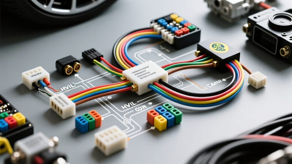
The High-Voltage Interlock Loop (HVIL) is a critical safety circuit that immediately opens the main battery contactors if any HV connector is unplugged. When using industry-standard Amphenol SurLok Plus or TE Connectivity HV connectors, the HVIL circuit utilizes a small 2-pin auxiliary connector. Below is the standard HVIL pinout configuration integrated into the lotus auto electric safety loop:
| Pin Number | Wire Color | Function | Destination / Logic |
|---|---|---|---|
| Pin 1 | Red (18 AWG) | HVIL Out (+) | Routes from BMS Master to first HV connector |
| Pin 2 | Black (18 AWG) | HVIL In (-) | Returns to BMS Master; completes the safety loop |
If the loop is broken, the BMS instantly drops the main precharge and pack contactors, de-energizing the HV cables within milliseconds. Ensure the HVIL loop is wired in series through the service disconnect, battery lid, and inverter cover.
Integrating the Lotus CAN Bus with the EV VCU
Modern Lotus vehicles (from the Toyota 2ZZ-GE era onward) rely heavily on Controller Area Network (CAN) bus communication. To retain the factory instrument cluster, steering wheel controls, and immobilizer bypass, your EV Vehicle Control Unit (VCU) must interface directly with the Lotus CAN network. As outlined in the ISO 11898 standard for CAN bus architecture, the network requires a twisted pair of wires and 120-ohm termination resistors at both ends of the bus.
On the Lotus OBD2 diagnostic port (which taps directly into the main CAN backbone), the standard pinout is:
- CAN-High (Pin 6): Typically White/Red or Yellow wire.
- CAN-Low (Pin 14): Typically White/Brown or Green wire.
To integrate the EV VCU, you will splice into these lines using a proper CAN bus junction block or Deutsch DT connectors. Do not use solder-and-tape methods, as the high-frequency signaling of the CAN bus is susceptible to capacitance changes and signal reflection. Your VCU must be programmed to transmit the specific hexadecimal CAN IDs that the Lotus dash cluster expects for RPM (mapped to motor shaft speed), coolant temperature (mapped to inverter/motor temp), and fuel level (mapped to battery State of Charge).
Electronic Throttle Pedal Signal Mapping
The Lotus Elise S2 and Exige utilize a Siemens/VDO electronic throttle pedal assembly. Unlike older cable-driven throttles, this pedal outputs dual analog voltage signals that must be read by the EV motor controller. The pedal connector typically features 6 pins:
- Pin 1: 5V Reference (Signal 1)
- Pin 2: Sensor Ground (Signal 1)
- Pin 3: Throttle Signal 1 (0.5V - 4.5V)
- Pin 4: 5V Reference (Signal 2)
- Pin 5: Sensor Ground (Signal 2)
- Pin 6: Throttle Signal 2 (0.25V - 2.25V, typically half of Signal 1)
When wiring this to your EV inverter, you must configure the inverter's software to recognize the dual-redundant potentiometer mapping. If the VCU detects a discrepancy greater than 5% between Signal 1 and Signal 2, it will trigger a torque-reduction limp mode to prevent unintended acceleration.
DC-DC Converter and 12V Distribution Upgrades
With the ICE alternator removed, the lotus auto electric build requires a high-capacity DC-DC converter to step down the HV battery pack voltage (typically 300V-400V) to 14.2V for the LV system. A 2.5kW to 3.0kW isolated DC-DC converter is recommended to handle the Lotus's electric water pump, HVAC blower motor, headlights, and ECU requirements.
Wire the DC-DC output to a marine-grade or motorsport Power Distribution Module (PDM) rather than the factory Lotus fuse box. A solid-state PDM allows you to programmatically sequence the 12V loads. For example, you can program the PDM to power the battery cooling pumps 3 seconds before the main HV contactors close, ensuring thermal management is active during the precharge cycle.
Aluminum Chassis Grounding and Galvanic Corrosion
One of the most common failure points in a lotus auto electric modification is improper grounding. The aluminum chassis is highly susceptible to galvanic corrosion when copper ground straps are bolted directly to it, especially in the presence of moisture and road salt. This corrosion creates high-resistance ground paths, leading to erratic sensor readings and CAN bus communication faults.
To prevent this, all 12V and HV shield grounds must be terminated using stainless steel rivnuts or helicoils installed into the aluminum chassis. Apply a generous layer of anti-corrosion joint compound (such as Noalox) between the copper lug, the stainless steel bolt, and the aluminum surface. Never rely on the aluminum tub itself as a high-current ground return path; always run dedicated 4 AWG or 2 AWG ground cables back to the main battery negative terminal or a centralized copper ground busbar.
Final Isolation Testing and Safety Protocols
Before applying HV power, a megohmmeter (Megger) test is mandatory to verify the dielectric isolation of the lotus auto electric system. Disconnect the battery pack and apply a 500V DC test potential between the HV positive/negative busbars and the bare aluminum chassis. According to Orion BMS technical guidelines and standard EV safety protocols, the insulation resistance must read a minimum of 500 ohms per volt of the battery pack (e.g., a 400V pack requires at least 200 kΩ of isolation resistance). If the resistance is lower, you have a pinched HV cable, a compromised connector seal, or an inverter coolant leak that must be diagnosed and rectified before the vehicle is energized. Proper execution of these wiring protocols ensures your EV conversion is not only blisteringly fast but fundamentally safe and reliable.