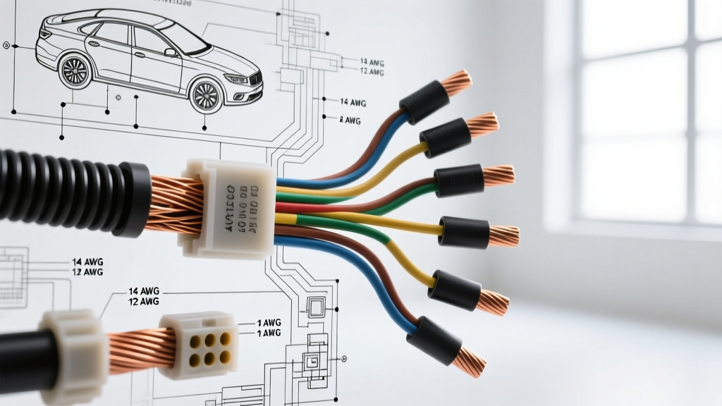
The Architecture of Car Electrical System Repair Cost
When evaluating the car electrical system repair cost for modern vehicles, consumers and technicians alike often focus solely on the price of replacement modules or sensors. However, from a technical specification perspective, the true cost of electrical repair is dictated by circuit complexity, diagnostic labor matrices, wiring harness material specifications, and OEM versus point-to-point repair economics. Professional repair facilities rely on flat-rate manuals (such as Mitchell1 or Alldata) which calculate labor based on the physical routing of harnesses, the cavity count of connectors, and the required SAE J1128 compliance for primary automotive cable.
This technical reference breaks down the actual cost drivers in automotive electrical repair, providing a specification matrix for diagnostic labor, wire gauge (AWG) material costs, and the precise engineering parameters required to fix high-amperage and multiplex network faults correctly.
Diagnostic Labor Matrices: Where the Cost Originates
The most significant variable in any car electrical system repair cost is diagnostic time. Unlike mechanical repairs where a failed water pump has a fixed book time, electrical faults require systematic isolation. The table below outlines standard diagnostic labor allocations for common electrical architectures based on industry-standard flat-rate guides.
| Diagnostic Operation | Circuit Type | Standard Labor Time | Technical Complexity & Tooling |
|---|---|---|---|
| Parasitic Draw Isolation | 12V Power Distribution | 1.5 - 3.0 Hours | Requires inline ammeter (10A max), fused jumper harness, and module sleep-cycle monitoring (up to 45 mins). |
| CAN Bus Short-to-Ground | Multiplex Network | 2.0 - 4.5 Hours | Requires digital storage oscilloscope (DSO), breakout boxes, and systematic node-by-node depinning. |
| Intermittent Sensor Signal | 5V Reference / Return | 1.0 - 2.5 Hours | Requires back-probing, voltage drop testing under load, and wiggle-testing harness flex points. |
| PCM/ECM Communication Loss | High-Speed GMLAN / HS-CAN | 1.5 - 3.5 Hours | Requires checking termination resistance (60 ohms), DLC Pin 6/14 continuity, and module wake-up signals. |
As illustrated, a CAN bus fault can easily incur 4.5 hours of labor before a single part is ordered. At an average shop rate of $150/hour, the diagnostic portion of the car electrical system repair cost alone reaches $675. This justifies the necessity of using breakout boxes and DSOs rather than relying on guesswork and parts swapping.
Wiring Harness & Component Material Specifications
Once the fault is isolated to a specific circuit, the material cost varies wildly depending on whether the technician utilizes an OEM pigtail, a complete harness assembly, or bulk automotive-grade wire. According to ISO 16750-2 environmental testing standards for automotive electrical equipment, using non-spec household wire (like THHN) will result in insulation melting and copper oxidation due to under-hood thermal cycling and fluid exposure.
OEM Harness vs. Point-to-Point Repair Matrix
| Component / Circuit | AWG Size | Connector Type | OEM Harness Cost | Bulk Repair Material Cost |
|---|---|---|---|---|
| Alternator B+ Power Feed | 4 AWG to 1/0 AWG | M8 / M10 Ring Terminal | $180 - $450 | $25 - $60 (TXL Wire + Adhesive Heat Shrink) |
| O2 Sensor Heater Circuit | 18 AWG | Metripack 280 / Weather-Pack | $65 - $120 (Pigtail) | $8 (Terminals, Seals, Wire) |
| Fuel Injector Harness | 20 AWG | USCAR / EV6 Connector | $350 - $800 (Full Bank) | $45 (Connectors + Pigtails) |
| CAN Bus Trunk Harness | 22 AWG (Twisted) | Deutsch DT / OEM Splice | $900 - $2,200 | $15 (Shielded Twisted Pair + Solder Sleeves) |
The data clearly shows that mastering point-to-point repair techniques drastically reduces the overall car electrical system repair cost for the end user while maintaining OEM reliability, provided the correct ASE-certified crimping and soldering procedures are followed.
High-Amperage Circuits: Starter & Alternator Economics
High-amperage circuits are responsible for some of the most catastrophic electrical fires when repaired improperly. The starter motor and alternator B+ terminals routinely handle 150A to 250A+ under peak load.
- Wire Specification: Must use SAE J1128 compliant TXL (Thin-wall cross-linked) or SXL (Specialty cross-linked) copper wire. For a 200A alternator upgrade, 1/0 AWG wire is required to prevent voltage drop exceeding 0.2V over a 6-foot run.
- Termination: Open-barrel crimps are insufficient for 4 AWG and larger. Closed-end copper lugs must be used, crimped with a hydraulic hex-die press, and sealed with dual-wall, adhesive-lined polyolefin heat shrink to prevent galvanic corrosion.
- Torque Specifications: The B+ terminal nut on a standard Denso or Bosch alternator (typically an M8 thread) must be torqued to 15-20 Nm. Under-torquing creates high resistance, leading to localized melting of the plastic insulator boot and eventual short-to-ground.
Replacing a melted engine harness due to a loose B+ terminal can push the car electrical system repair cost past $2,500 in labor and parts. Proper torque and die-crimping eliminate this failure mode entirely.
Multiplex Networks: CAN Bus Faults and Pinout Specs
Modern vehicles utilize Controller Area Network (CAN) buses to facilitate module-to-module communication. A single chafed wire can bring down the entire powertrain or body control network, resulting in a no-start condition. The repair cost here is heavily weighted toward the technician's understanding of network topology.
Common CAN Bus Pinouts and Wire Colors
| Manufacturer | Network | DLC Pin (High / Low) | Wire Colors (High / Low) | Termination Resistance |
|---|---|---|---|---|
| General Motors (GMLAN) | High-Speed | Pin 6 / Pin 14 | Dark Green / Dark Blue | 60 Ohms (Two 120-Ohm Resistors in Parallel) |
| Ford (HS-CAN / MS-CAN) | High-Speed | Pin 6 / Pin 14 | White/Blue / White | 60 Ohms (Integrated in PCM & BCM) |
| Chrysler (C-Bus / I-Bus) | Standard CAN | Pin 6 / Pin 14 | White/Dark Green / White/Dark Blue | 60 Ohms (Terminating nodes vary by year) |
Technical Repair Protocol: When repairing a severed CAN bus twisted pair, the twist rate (typically 1 twist per inch) must be maintained to preserve the common-mode noise rejection. Splicing must be done using solder-seal heat shrink connectors or ultrasonic welding. Standard butt-crimps introduce micro-ohm resistance variations that cause signal reflection and bus-off errors. A technician who understands this can repair a $1,500 harness issue for under $30 in materials and 1.5 hours of labor.
Integrated Power Modules (IPM/TIPM) Internal Failures
A frequent driver of high electrical repair costs in vehicles from 2007-2015 (notably Chrysler/Dodge platforms) is the Totally Integrated Power Module (TIPM). These fuse boxes contain internal PCB traces and surface-mount relays that fail due to thermal cycling and moisture ingress.
Rather than replacing the entire TIPM (which costs $800-$1,200 and requires complex VIN-matching and proxy alignments), advanced electrical technicians perform internal bypasses. For example, the internal fuel pump relay frequently fails. By accessing the underside of the PCB, a technician can solder a 14 AWG jumper wire from a switched 12V accessory fuse slot directly to the fuel pump output trace, utilizing an external standard 30A automotive relay. This technical workaround reduces the car electrical system repair cost by over 70% while providing a more reliable, serviceable circuit.
Summary of Repair Economics
Ultimately, the car electrical system repair cost is a function of diagnostic accuracy and material science. By adhering to SAE wiring standards, utilizing proper DSO diagnostics, and executing OEM-specification splices, technicians can mitigate the exorbitant costs associated with full harness replacements and module programming. Understanding the underlying architecture—from AWG ampacity limits to CAN bus termination physics—is the only way to deliver cost-effective, permanent electrical repairs in modern automotive environments.