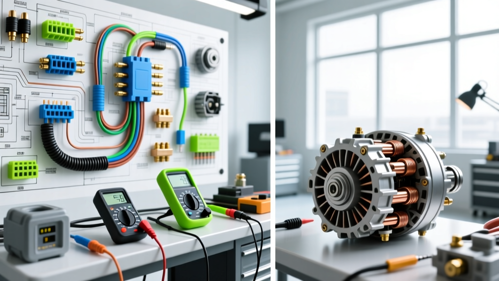
The Hughes Auto Electric Benchmark for Component Rebuilding
When evaluating the benchmark set by specialized, legacy rebuilders like Hughes Auto Electric, automotive technicians must look beyond simple pass/fail bench tests. True auto-electric mastery requires a granular understanding of electromagnetic tolerances, thermal limits, and precise circuit architecture. Whether you are rebuilding a classic Delco Remy SI series alternator or diagnosing a modern Denso SC14 high-output unit, adhering to rigorous specification references is the only way to guarantee longevity and prevent catastrophic wiring harness failures. This technical reference outlines the exact diagnostic procedures, bench-testing parameters, and high-amperage wiring protocols required to meet top-tier auto electric standards.
Alternator Component Diagnostics and Bench Testing
Before an alternator is subjected to a dynamic load test on a HEC-350 or Rottler test bench, every internal sub-assembly must be statically verified using a high-precision digital multimeter (DMM) such as a Fluke 88V. Reputable auto electric shops reject components that fall even marginally outside of OEM resistance and leakage tolerances, as these micro-faults manifest as severe voltage ripple under heavy electrical loads.
Rotor, Stator, and Rectifier Bridge Tolerances
The rotor assembly (field coil) is tested for continuity across the copper slip rings. A reading outside the 2.5 to 4.5 ohm window indicates either a shorted winding or a high-resistance corrosion fault at the brush contact point. The stator must be evaluated for both phase continuity and ground insulation. In a Wye-configured stator, you must verify continuity between all three output leads while confirming infinite resistance (OL) between any lead and the laminated steel core. Finally, the rectifier bridge diode trio must be tested in both forward and reverse bias to detect thermal fatigue and leakage current.
| Component | Test Parameter | Acceptable Specification | Failure Mode Indicator |
|---|---|---|---|
| Rotor (Field Coil) | Slip Ring Resistance | 2.5 Ω - 4.5 Ω | < 2.0 Ω (Short), > 5.0 Ω (Open/Corrosion) |
| Stator (Wye/Delta) | Phase Continuity | < 0.5 Ω between leads | OL (Open winding) |
| Stator Core | Insulation to Ground | Infinite (OL) | Any continuity to steel core (Short to ground) |
| Rectifier Bridge | Diode Forward Bias | 0.40V - 0.65V | 0.00V (Shorted Diode) |
| Rectifier Bridge | Diode Reverse Bias | OL (Open Loop) | Any voltage reading (Leaking Diode) |
High-Output Alternator Wiring and AWG Upgrades
A common failure point in custom auto-electric installations is the retention of factory wiring when upgrading to a high-output alternator. Factory 8 AWG or 6 AWG charge cables are rated for roughly 60 to 80 amps continuous. Pushing 150+ amps through undersized copper results in severe voltage drop, excessive heat generation, and eventual insulation meltdown. When executing an upgrade to a 200A+ alternator, the entire charge circuit must be rebuilt using fine-strand welding cable and high-amperage overcurrent protection.
Cable Sizing, Fusing, and Termination Protocols
For high-amperage circuits, standard stranded THHN wire is insufficient due to its inability to handle high-frequency engine bay vibration and extreme thermal cycling. Fine-strand, pure copper welding cable (SAE J1128 compliant) is mandatory. All terminations must utilize adhesive-lined, dual-wall heat shrink ring terminals (3/8' inner diameter for standard B+ studs) crimped with a minimum 12-ton hydraulic crimper to ensure a cold-weld connection. Soldering is strictly prohibited on high-current B+ circuits, as the solder can wick into the wire strands, creating a rigid stress point that will fracture under engine vibration.
| Alternator Max Output | Minimum Wire Gauge (AWG) | Required Fuse Type & Rating | Terminal Specification |
|---|---|---|---|
| 100A - 140A | 4 AWG Fine Strand | 150A ANL or Class T | Adhesive-Lined Heat Shrink, 5/16' Ring |
| 150A - 180A | 1/0 AWG Fine Strand | 200A ANL or Class T | Adhesive-Lined Heat Shrink, 3/8' Ring |
| 190A - 240A | 2/0 AWG Fine Strand | 250A Class T | Adhesive-Lined Heat Shrink, 3/8' Ring |
| 250A - 320A | 4/0 AWG Fine Strand | 350A Class T | Adhesive-Lined Heat Shrink, 1/2' Ring |
Voltage Regulator Pinouts and Remote Sense Wiring
Modern internally regulated alternators rely on precise voltage sense feedback to adjust the rotor field current. A classic example is the Delco CS130D or the Denso SC series. These units utilize a multi-pin connector where the 'S' (Sense) terminal monitors the actual voltage at the battery post or main distribution block. If the sense wire is damaged, corroded, or incorrectly spliced, the regulator will read artificially low voltage and overcharge the system, boiling the battery electrolyte and destroying sensitive ECU modules.
To prevent this, the remote sense circuit must be wired using a dedicated 14 AWG or 12 AWG primary wire (typically Red with a White tracer), routed away from high-tension ignition wires to prevent electromagnetic interference (EMI). The sense wire must be fused at 10A within 6 inches of the battery connection point. Voltage drop across the sense wire at a 10A simulated load must not exceed 0.10V. The 'L' (Lamp/Ignition) terminal requires a 12V switched ignition source, often routed through a 510-ohm resistor or a standard 194 incandescent dash bulb to provide the initial excitation current required to 'turn on' the alternator's magnetic field.
Starter Motor Load Testing and Voltage Drop Protocols
Just as with alternators, evaluating starter motors requires strict adherence to cranking circuit voltage drop limits. According to SAE J541 standards for voltage drop, the maximum allowable voltage drop on the positive cranking cable (from battery post to starter B+ stud) is 0.50V, and the negative ground circuit (from battery negative post to starter housing) must not exceed 0.20V. Exceeding these thresholds indicates high resistance at the cable lugs, corroded battery clamps, or a failing engine-to-chassis ground strap.
Cranking Circuit Voltage Drop Limits
When bench-testing a 1.4kW Permanent Magnet Gear Reduction (PMGR) starter, the no-load amp draw should typically fall between 60A and 90A at 12.5V, spinning at roughly 5,000 to 6,500 RPM. Under simulated engine load, the amp draw will spike to 120A - 160A, and the voltage at the starter B+ terminal must not drop below 9.6V. If the starter draws excessive amperage (e.g., > 200A) while rotating slowly, the armature is likely dragging against the field magnets due to worn bushings or a warped armature shaft. Furthermore, the B+ terminal nut on the starter solenoid must be torqued precisely to 9-12 Nm (80-106 in-lbs). Over-torquing this nut will crack the bakelite insulator washer, creating a direct short to the starter housing and resulting in an immediate, un-fused electrical fire.
Authoritative References and Industry Standards
For further technical validation and advanced diagnostic flowcharts, technicians should consult established automotive electrical engineering resources. The diagnostic methodologies outlined above align with the rigorous rebuilding and testing protocols championed by legacy institutions like Hughes Auto Electric, ensuring that every component leaving the bench is capable of surviving extreme under-hood environments.
- SAE J541: Voltage Drop Standards for Heavy Duty and Passenger Vehicle Cranking Circuits - Society of Automotive Engineers.
- Rick's Motorsport Electrics Technical Tips - Industry-leading reference for stator, rectifier, and regulator diagnostic procedures and DMM testing methodologies.
- Bosch Mobility Solutions: Starter Motor Engineering & PMGR Specifications - OEM engineering data on gear-reduction starter tolerances and load testing.