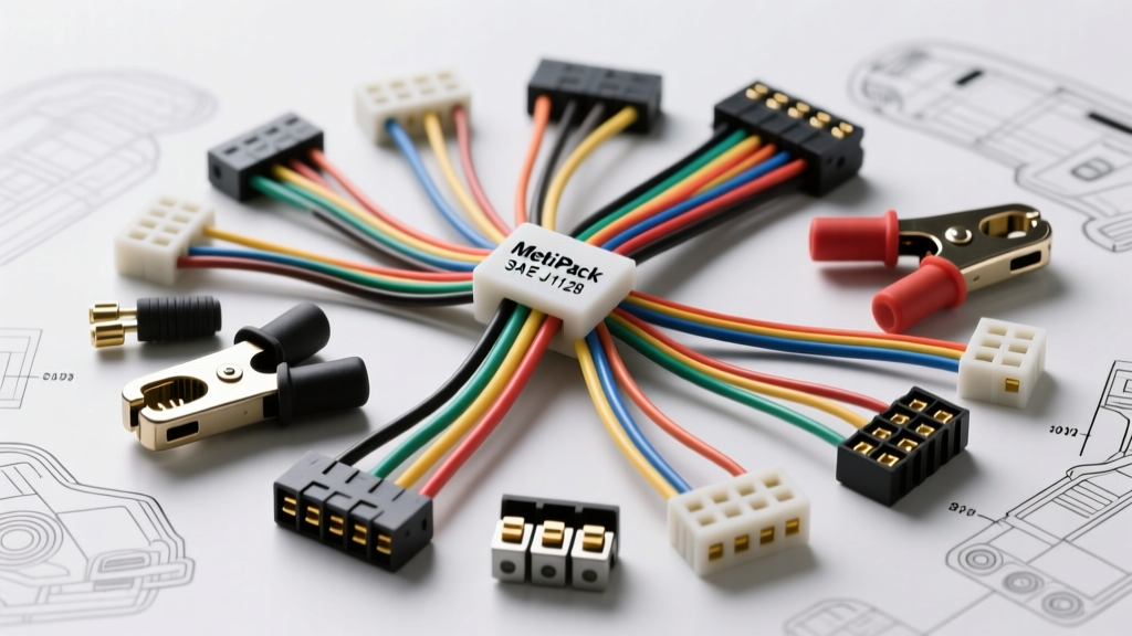
Engineering Reliable Harnesses: The Science of Component Selection
Knowing how to properly select auto electrical components is the difference between a reliable, OEM-grade wiring harness and a rolling fire hazard. Automotive environments subject electrical systems to extreme thermal cycling, high-frequency vibrations, and corrosive chemical exposure. Whether you are building a custom ECU harness, upgrading an alternator output circuit, or integrating aftermarket electric AC compressors, generic hardware store components will fail. This technical reference guide provides the exact specifications, SAE standards, and material science required to select auto electrical wiring, terminals, and overcurrent protection for 12V and 24V vehicle architectures.
Wire Gauge Selection: SAE J1128 vs. AWG Standards
Automotive wire is not classified strictly by American Wire Gauge (AWG); it is governed by the SAE J1128 standard, which dictates conductor stranding, insulation thickness, and thermal ratings. While AWG defines the cross-sectional copper area, SAE standards define the insulation chemistry required to survive under-hood temperatures.
Standard PVC-insulated wires (Types GPT, TWP, and HDT) are rated for continuous operation up to 105°C. However, modern engine bays frequently exceed this threshold near exhaust manifolds and turbochargers. For high-heat zones, you must select cross-linked polyethylene (XLPE) insulated wires (Types SXL, GXL, and TXL), which are rated for 125°C continuous and 150°C excursion. TXL (Thin-wall cross-linked) is the industry standard for modern OEM harnesses because it reduces harness weight and diameter while maintaining high thermal resistance.
Chassis Wiring Ampacity Reference Table
The following table outlines the maximum continuous current capacity for single conductors in free air at an ambient temperature of 20°C. When bundling wires, you must apply a derating factor of 0.80 for 3-5 wires, and 0.60 for 6 or more wires in a single loom.
| AWG Size | SAE Metric (mm²) | Max Ampacity (Free Air) | Typical Application |
|---|---|---|---|
| 18 AWG | 0.80 mm² | 6 Amps | ECU sensors, CAN bus, low-current lighting |
| 16 AWG | 1.00 mm² | 10 Amps | Instrument clusters, relays, interior lighting |
| 14 AWG | 2.00 mm² | 15 Amps | Fuel pumps, horn circuits, power windows |
| 12 AWG | 3.00 mm² | 20 Amps | Headlights, HVAC blower motors, 12V sockets |
| 10 AWG | 5.00 mm² | 30 Amps | ABS modules, high-amperage cooling fans |
| 8 AWG | 8.00 mm² | 40 Amps | Alternator B+ output, starter solenoid feeds |
| 4 AWG | 20.00 mm² | 100 Amps | Main battery feeds, high-output alternators |
Voltage Drop Calculations for Long Harness Runs
Selecting the correct wire gauge requires calculating voltage drop, especially for long runs from the front-mounted battery to rear-mounted fuel pumps or amplifiers. Sensitive automotive electronics, such as oxygen sensors and MAF sensors, require a strict maximum voltage drop of 3% (0.36V on a 12V system). Lighting and resistive loads can tolerate up to a 10% drop.
Use the following formula to calculate voltage drop: VD = (2 × L × I × R) / 1000, where L is the one-way length in feet, I is the current in amps, and R is the wire resistance per 1,000 feet. For example, running a 15A electric fuel pump 12 feet using 14 AWG wire (2.525 ohms/1000ft) results in a voltage drop of 0.90V. This is a 7.5% drop, which is unacceptable for a modern PWM-controlled fuel pump. Upgrading to 10 AWG wire reduces the drop to 0.38V (3.1%), ensuring optimal pump performance.
Terminal and Connector Specifications
The connector ecosystem in automotive electrical systems is vast. When you select auto electrical connectors, you must match the environmental sealing requirements and current density to the specific circuit. Aptiv Connection Systems (formerly Delphi) and Deutsch are the dominant standards in OEM and motorsport applications.
Terminal Plating Metallurgy
Terminal plating is critical for preventing fretting corrosion and maintaining low contact resistance. Never use tin-plated terminals for low-current, low-voltage sensor circuits (under 1 Amp). Tin oxidizes rapidly, and low-current circuits lack the electrical force to break through the tin oxide layer, resulting in erratic sensor data. Gold-plated terminals are mandatory for dry circuits, ECU logic pins, and CAN bus lines. Silver plating is reserved for high-current applications (40A+) due to its superior thermal conductivity and resistance to arc erosion.
Connector Series Comparison
| Connector Series | Current Rating | Sealing / IP Rating | Primary Use Case |
|---|---|---|---|
| Aptiv Metri-Pack 150 | 14A Max | IP67 (Sealed) | Sensors, injectors, ECU connections |
| Aptiv Metri-Pack 280 | 30A Max | IP67 (Sealed) | ABS modules, transmission solenoids |
| Aptiv Metri-Pack 630 | 46A Max | Unsealed / Sealed | HVAC blowers, high-current relays |
| Deutsch DT Series | 13A Max | IP68 / IP69K | Motorsport, heavy machinery, exterior lighting |
| Deutsch DTM Series | 7.5A Max | IP68 / IP69K | Compact ECU harnesses, tight-space sensor looms |
Crimping Standards and USCAR-21 Validation
A proper crimp creates a cold-weld between the terminal barrel and the copper strands, eliminating voids where moisture could ingress. The automotive industry relies on the SAE USCAR-21 standard to validate crimp profiles. A perfect crimp exhibits a visible "conductor bellmouth" at the front of the terminal and an "insulation bellmouth" at the rear. The conductor must be flush with the front of the terminal barrel, but never protrude past the mating interface.
USCAR-21 mandates specific pull-out force requirements to ensure the crimp will survive vehicle vibration over a 15-year lifecycle. Using a calibrated crimp press with the correct die profile is mandatory; hand-crimping tools rarely achieve the precise compression ratio required for USCAR compliance on high-strand-count automotive wire.
USCAR-21 Minimum Crimp Pull-Out Forces
| Wire Size (AWG / mm²) | Minimum Pull Force (Newtons) | Minimum Pull Force (Pounds) |
|---|---|---|
| 22 AWG (0.35 mm²) | 50 N | 11.2 lbs |
| 18 AWG (0.80 mm²) | 80 N | 18.0 lbs |
| 14 AWG (2.00 mm²) | 150 N | 33.7 lbs |
| 12 AWG (3.00 mm²) | 200 N | 45.0 lbs |
| 10 AWG (5.00 mm²) | 250 N | 56.2 lbs |
Overcurrent Protection: Fuse Sizing and Time-Current Curves
Selecting the correct fuse requires understanding time-current curves, not just the nominal amperage rating. Automotive fuses are categorized by their physical footprint and blow characteristics. The ATO (standard blade) and Mini fuses are fast-acting, designed to protect sensitive solid-state electronics and thin-gauge wiring from short circuits. MAXI fuses handle higher currents (20A-60A) for heavy accessories. MIDI (or AMI) and Mega fuses are used for main battery feeds and high-output alternator circuits (80A-250A).
When protecting inductive loads like electric cooling fans or fuel pumps, you must account for inrush current. A 15A continuous draw fan may pull 35A for the first 200 milliseconds upon startup. If you use a standard fast-blow 15A ATO fuse, it will nuisance-blow repeatedly. In these scenarios, you must select a slow-blow (time-delay) fuse or size the fast-blow fuse to 150% of the continuous load while ensuring the wire gauge can safely handle the higher fault-clearing time.
Real-World Failure Modes and Diagnostic Insights
Even with premium components, improper installation leads to predictable failure modes. Fretting corrosion occurs when terminals are subjected to high-frequency, low-amplitude vibrations (common in diesel engines and near suspension components). This micro-movement wears away the terminal plating, exposing base metals to oxidation. The fix is to use connectors with high normal-force terminal designs (like the Aptiv 280 series) and apply a dielectric grease specifically formulated to dampen vibration without insulating the contact patch.
Galvanic corrosion is another critical failure mode, particularly when integrating aftermarket aluminum-bodied components with copper wiring. If moisture bridges the gap between copper and aluminum, a galvanic cell forms, rapidly destroying the aluminum. Always use tinned copper wire and apply marine-grade heat shrink with adhesive-lined polyolefin to create a hermetic, moisture-proof seal over the crimp joint. Avoid standard PVC heat shrink in under-hood or under-chassis environments, as it will crack and wick moisture directly into the copper strands via capillary action.
Summary
Building a resilient automotive electrical system requires strict adherence to SAE and USCAR engineering standards. By carefully calculating voltage drop, selecting the correct XLPE wire insulation, matching terminal metallurgy to the circuit's current profile, and validating crimps against USCAR-21 pull-test metrics, you ensure the electrical architecture will survive the harsh realities of the automotive environment.