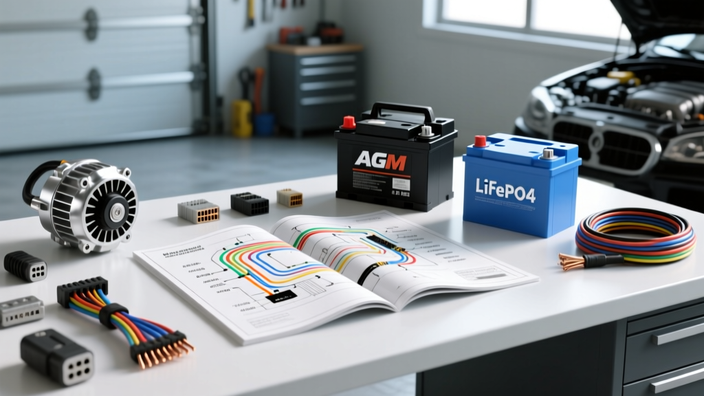
Assessing Your Car Electrical System Baseline
The modern car electrical system is engineered primarily to support OEM ECU requirements, fuel injection, ignition, and standard comfort accessories. When you introduce high-draw auxiliary loads—such as off-road LED light bars, heavy-duty winches, mobile ham radios, or competition-level audio amplifiers—the factory 100A to 130A alternator and standard flooded lead-acid battery quickly become the weakest links. Upgrading requires a holistic approach. This guide compares the critical components required to build a robust, high-output electrical architecture, focusing on alternator topologies, battery chemistries, and SAE-compliant wiring infrastructures.
Alternator Selection: OEM vs. High-Output Aftermarket
The alternator is the heart of any car electrical system. Factory units typically utilize a Lundell (claw-pole) stator design, which is cost-effective but suffers from poor low-RPM output and high thermal degradation. High-output aftermarket alternators utilize hairpin stator windings and high-density rectifier bridges to maximize amperage at idle.
Alternator Topology Comparison
| Specification | OEM Claw-Pole (e.g., 130A Delco) | High-Output Hairpin (e.g., 250A Denso-Style) |
|---|---|---|
| Idle Output (800 RPM) | ~45A (35% of rated) | ~180A (72% of rated) |
| Max Output RPM | ~2,500 Alternator RPM | ~1,800 Alternator RPM |
| Stator Winding | Round wire, lower slot fill | Flat copper hairpin, 95%+ slot fill |
| Thermal Management | Internal fan, prone to heat soak | Dual internal/external fans, optimized airflow |
| Regulator Type | Internal, fixed voltage curve | External or smart internal, temp-compensated |
Exciter and Sense Pin Configurations
When wiring a high-output alternator, understanding the regulator plug is critical. The ubiquitous Denso-style 3-pin connector features specific circuits:
- Pin 1 (L / Ignition): Typically a white or black/white wire. Provides the initial 12V excitation signal from the ignition switch to 'wake up' the regulator. Must be routed through a 5A fuse.
- Pin 2 (S / Sense): Typically a red wire. This is the voltage sense wire. It must be connected directly to the positive battery terminal or main distribution bus. Connecting it to the alternator B+ post will cause the regulator to read artificially high voltages due to voltage drop across the charge cable, resulting in undercharging the battery.
- Pin 3 (P / Phase): Rarely used in standard automotive applications; provides a tachometer signal derived from the stator AC phase.
Expert Tip: When upgrading to a 250A+ alternator, the factory B+ charge wire (often 6 AWG or 4 AWG) is a fire hazard. Upgrade the main charge cable to 1/0 AWG and torque the B+ post nut to 10-12 Nm (88-106 in-lbs) to prevent arcing.
Battery Chemistry Comparison: AGM vs. LiFePO4
The battery acts as the chemical capacitor in your car electrical system, absorbing alternator ripple current and supplying peak amperage during transient loads (like winching). According to Victron Energy's Wiring Unlimited guide, selecting the right chemistry dictates your entire charging profile.
AGM vs. Lithium Iron Phosphate (LiFePO4)
| Metric | AGM (Absorbent Glass Mat) | LiFePO4 (with BMS) |
|---|---|---|
| Internal Resistance | ~2.5 - 4.0 mΩ | ~0.5 - 1.0 mΩ |
| Voltage Sag under 100A Load | Drops to ~11.8V | Remains >13.2V |
| Absorption Voltage | 14.4V - 14.7V | 14.2V - 14.6V |
| Weight (Group 34) | ~45 lbs | ~22 lbs |
| Alternator Strain | Moderate (tapers off at 80% SOC) | High (accepts max amps until 99% SOC) |
Selection Criteria: If you are running a high-output alternator without an external temperature-compensated regulator, stick to AGM. LiFePO4 batteries have such low internal resistance that they will demand the alternator's maximum output continuously, potentially burning out the alternator's diode bridge. If you choose LiFePO4, you must install an external smart regulator (like a Wakespeed WS500) or an alternator protection module to throttle field current and prevent thermal destruction.
Wiring Infrastructure: AWG Sizing and Terminal Selection
A common failure point in modified car electrical systems is the use of undersized or poorly terminated wiring. When purchasing wire, you must understand the difference between AWG (American Wire Gauge) and SAE (Society of Automotive Engineers) sizing. As outlined in the SAE J1128 standard for low-tension battery cables, SAE wire contains significantly less copper than AWG wire of the same nominal size.
AWG vs. SAE Strand Count (1/0 Gauge Example)
- 1/0 AWG (Marine/Premium): ~1,056 strands of 30 AWG copper. Cross-sectional area: ~53.5 mm². Ampacity (chassis): 325A.
- 1/0 SAE (Standard Automotive): ~486 strands of 30 AWG copper. Cross-sectional area: ~42.4 mm². Ampacity (chassis): ~260A.
For high-draw auxiliary circuits, always specify Type 3 Marine-Grade AWG wire. The individual copper strands are tinned to resist galvanic corrosion and electrolytic creep, which is vital in the harsh under-hood environment.
Termination and Crimping Standards
Soldering high-amperage automotive terminals is strictly prohibited by aerospace and high-end automotive standards. Solder wicks into the wire strands, creating a rigid point that will inevitably fatigue and snap under engine vibration. Furthermore, solder melts at ~360°F (182°C), well within the temperature range of a heat-soaked engine bay.
The Correct Method:
- Strip the wire using a precision gauge stripper to avoid nicking outer strands.
- Slide on a 3:1 shrink-ratio, adhesive-lined (marine) heat shrink tube.
- Use a heavy-duty, closed-barrel copper lug (e.g., Ancor or Tinned Copper DIN 46235).
- Crimp using a hydraulic or heavy mechanical hex-crimp tool to achieve a gas-tight, cold-weld connection.
- Apply heat until the adhesive sealant extrudes slightly from the terminal entry point, ensuring a waterproof seal against capillary action.
Circuit Protection and Fusing Strategies
The final piece of the car electrical system upgrade is overcurrent protection. The type of fuse you select must match the fault-current potential of your battery chemistry.
- ANL Fuses: Rated for 35A to 750A with an Ampere Interrupting Capacity (AIC) of 2,700A. Suitable for AGM and standard lead-acid batteries.
- Class T Fuses: Rated for 110A to 400A+ with an AIC of 20,000A. When a LiFePO4 battery experiences a dead short, its ultra-low internal resistance can deliver tens of thousands of amps instantaneously. An ANL fuse will literally explode and sustain a plasma arc under this fault load. Class T fuses feature a ceramic core and sand filler to safely extinguish high-energy lithium faults. Always use Class T fuses within 18 inches of the positive terminal on any LiFePO4 installation.
Summary: Building a Bulletproof Architecture
Upgrading your car electrical system is not merely about bolting on a larger alternator. It requires matching the alternator's output curve to the battery's acceptance rate, sizing the AWG wiring to handle continuous chassis amperage, and selecting the correct AIC-rated fusing for the specific chemistry. By adhering to SAE and AWG standards and utilizing proper hex-crimp terminations, you ensure that your vehicle's electrical architecture can reliably support heavy auxiliary loads for years to come. For further reading on heavy-duty charging systems, refer to the DC Power Inc. Technical Library for application-specific pulley ratio calculations and bracket alignment tolerances.