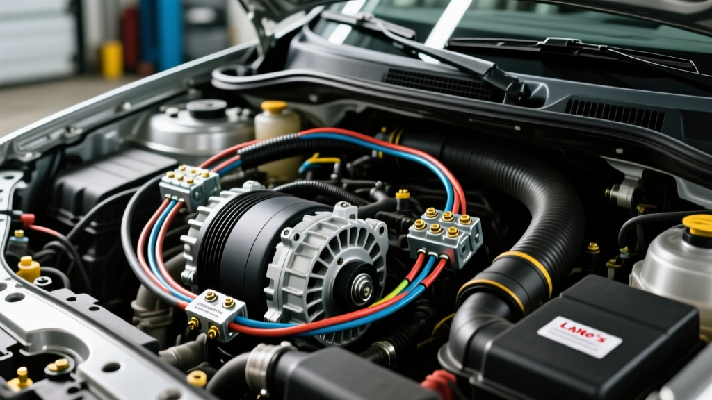
Upgrading Classic Charging Systems with Lalo's Auto Electric
When restoring a classic GM truck or hot rod, the factory 35-amp externally regulated alternator and brittle cloth-covered wiring are rarely sufficient for modern electrical loads. Upgrading to a comprehensive Lalo's Auto Electric main wiring harness and high-output internally regulated alternator kit solves voltage drops, dim headlights, and erratic ignition issues. Lalo's Auto Electric has built a strong reputation in the restomod community for providing robust, pre-terminated harnesses and 100A+ charging solutions designed specifically for classic V8 applications.
This practical installation guide covers the complete integration of a Lalo's Auto Electric 12-circuit under-dash harness paired with a GM 12SI-style 105-amp alternator upgrade. We will focus on proper wire routing, SAE-compliant crimping, precise pinout configurations, and critical voltage drop testing to ensure your vehicle's electrical architecture is reliable and safe.
Pre-Installation: Wire Standards and Tooling
Before touching a wrench, it is critical to understand the wire standards used in premium aftermarket kits. Authentic Lalo's Auto Electric harnesses utilize pure Oxygen-Free Copper (OFC) wire with GXL (Cross-linked polyethylene) insulation. According to the SAE J1128 standard, GXL wire is rated for continuous operation at 125°C and offers superior abrasion and chemical resistance compared to standard PVC wire. Never substitute OFC wire with Copper-Clad Aluminum (CCA), as CCA has higher resistance and is prone to galvanic corrosion at crimp joints.
Required Tools and Materials
- Digital Multimeter (DMM) with 0.1mV resolution for voltage drop testing
- Hydraulic wire crimper with hex dies (for 4 AWG to 8 AWG terminals)
- Ratcheting open-barrel crimper (for 10 AWG to 18 AWG weather-pack and spade terminals)
- Adhesive-lined dual-wall heat shrink (3M FP-301 or equivalent)
- 1.5-inch rubber firewall grommet and silicone dielectric grease
- Torque wrench (inch-pound and foot-pound capable)
Step-by-Step Installation Guide
Phase 1: Main Power Routing and Mega Fuse Integration
The foundation of the Lalo's Auto Electric system is the main 4 AWG positive feed. This cable carries the bulk current from the alternator to the battery and the main distribution block.
- Disconnect the Battery: Remove the negative battery cable first to eliminate short-circuit risks.
- Route the 4 AWG Main Feed: Route the 4 AWG OFC cable from the alternator output post, along the inner fender well, toward the battery. Secure the cable with UV-resistant nylon cable ties every 8 inches, ensuring it stays clear of exhaust headers and steering linkages.
- Install the Mega Fuse: Install a 150A ANL/Mega fuse holder on the 4 AWG cable. Critical safety rule: The fuse must be located within 18 inches of the positive battery terminal to protect the entire length of the main feed in the event of a dead short.
- Firewall Pass-Through: If routing a secondary 10 AWG ignition feed through the firewall, use a 1.5-inch rubber grommet. Apply silicone dielectric grease to the wire jacket before pulling it through to prevent insulation tearing.
Phase 2: Alternator Exciter and Sense Wire Routing
While many budget kits use a 'one-wire' alternator setup, the Lalo's Auto Electric kit utilizes a true 3-wire GM 12SI configuration for superior voltage regulation at idle. The alternator connector features two critical pins:
- Pin 1 (L - Lamp/Exciter): This wire (typically White or Brown, 14 AWG) connects to the dashboard charge indicator light and provides the initial excitation current to the voltage regulator. It must be routed through a 10-ohm, 2-watt resistor if an LED dash light is used, as LEDs do not draw enough current to excite the regulator.
- Pin 2 (S - Sense): This wire (typically Red, 10 AWG) tells the regulator what the actual system voltage is. Expert Tip: Do not loop this wire back to the alternator output post. Route the Pin 2 sense wire directly to the main power distribution block or the positive battery terminal. This forces the alternator to compensate for voltage drop across the 4 AWG main cable, ensuring your fuse block always receives a true 14.2V.
Mount the alternator to the engine block. For classic GM small-block applications, torque the lower pivot bolt to 37 lb-ft and the upper adjustment bracket bolt to 18 lb-ft. Use a Delco/Remy spec serpentine or V-belt, ensuring 1/2-inch of deflection at the midpoint of the longest belt span.
Phase 3: Under-Dash Fuse Block and Headlight Relays
Mount the Lalo's Auto Electric centralized fuse block under the dash, preferably on the driver's side kick panel or firewall. Connect the main 10 AWG ignition-switched feed to the 'IGN' terminal on the fuse block. For the headlight circuit, the kit includes a heavy-duty relay upgrade. Classic GM headlight switches are notorious for melting when running modern halogen or high-draw LED sealed beams. The relay harness uses 10 AWG feeds directly from the battery to the headlights, triggered by a low-current 16 AWG signal wire from the factory headlight switch, completely bypassing the high-amperage load from the dash.
Lalo's Auto Electric Pinout and Wire Color Reference
| Circuit Function | Wire Gauge | Color Code | Termination Type | Destination / Notes |
|---|---|---|---|---|
| Main Charging Feed | 4 AWG | Red (GXL) | 3/8" Ring Terminal | Alternator Post to Battery (+) via 150A Mega Fuse |
| Alternator Sense (Pin 2) | 10 AWG | Red | Female Spade / Ring | Alternator Plug to Fuse Block Main Batt Feed |
| Alternator Exciter (Pin 1) | 14 AWG | White | Female Spade | Alternator Plug to Dash Charge Lamp (via 10Ω resistor if LED) |
| Ignition Switch Feed | 10 AWG | Pink | Male Bullet / Spade | Ignition Switch 'BAT' to Fuse Block 'IGN' Bus |
| Headlight Relay Trigger | 16 AWG | Light Blue | Female Spade | Factory Headlight Switch to Relay Coil (85/86) |
| Engine Block Ground | 2 AWG | Black | 3/8" Ring Terminal | Battery (-) to Engine Block (Clean to bare metal) |
Troubleshooting Common Charging and Wiring Issues
Even with a premium Lalo's Auto Electric harness, installation errors can cause electrical gremlins. Use this diagnostic decision tree to resolve common issues post-installation:
Symptom: Alternator Whining Through the Stereo
- Cause: Alternator whine is almost always caused by a poor ground reference or an unshielded audio RCA cable running parallel to the 4 AWG main power wire.
- Fix: Verify the 2 AWG engine-to-chassis ground. Remove the ring terminal, sand the engine block and chassis mounting point to bare, shiny metal using 80-grit sandpaper, and re-torque. Re-route audio cables away from the main power harness.
Symptom: Dim Headlights and Low Voltage at Idle
- Cause: The voltage regulator is reading a false 'high' voltage and backing off the alternator output. This happens if the Pin 2 (Sense) wire is damaged, disconnected, or incorrectly looped back to the alternator output post while the main 4 AWG cable is experiencing a severe voltage drop.
- Fix: Perform a voltage drop test on the positive side. Set your DMM to DC Volts. Place the red probe on the alternator output post and the black probe on the positive battery terminal. Start the engine, turn on the headlights and HVAC blower to high, and rev to 1500 RPM. If the DMM reads more than 0.2V, your 4 AWG cable has high resistance (check for loose crimps or corroded ring terminals). If the cable is fine, ensure the Pin 2 sense wire is reading true battery voltage.
Symptom: Dash Charge Lamp Stays On After Engine Starts
- Cause: The Pin 1 (Exciter/Lamp) wire is shorted to ground, or the alternator internal diode trio is faulty.
- Fix: Unplug the 2-pin connector at the alternator. If the dash light turns off, the alternator is internally shorted and requires rebuilding. If the light stays on with the connector unplugged, trace the White Pin 1 wire back to the dash for a chafed short to ground.
Expert Tips for Long-Term Reliability
To ensure your Lalo's Auto Electric installation lasts for decades, always use adhesive-lined heat shrink on all ring and spade terminal crimps. The adhesive melts and seals the wire strands, preventing moisture ingress and the dreaded 'green crust' copper oxidation. Furthermore, label every wire at both ends using heat-shrink cable markers. When you are troubleshooting a blown fuse three years from now on the side of the road, those labels will be invaluable. Finally, apply a light coat of dielectric grease to all weather-pack and bulkhead connectors before mating them to ensure a moisture-tight seal.