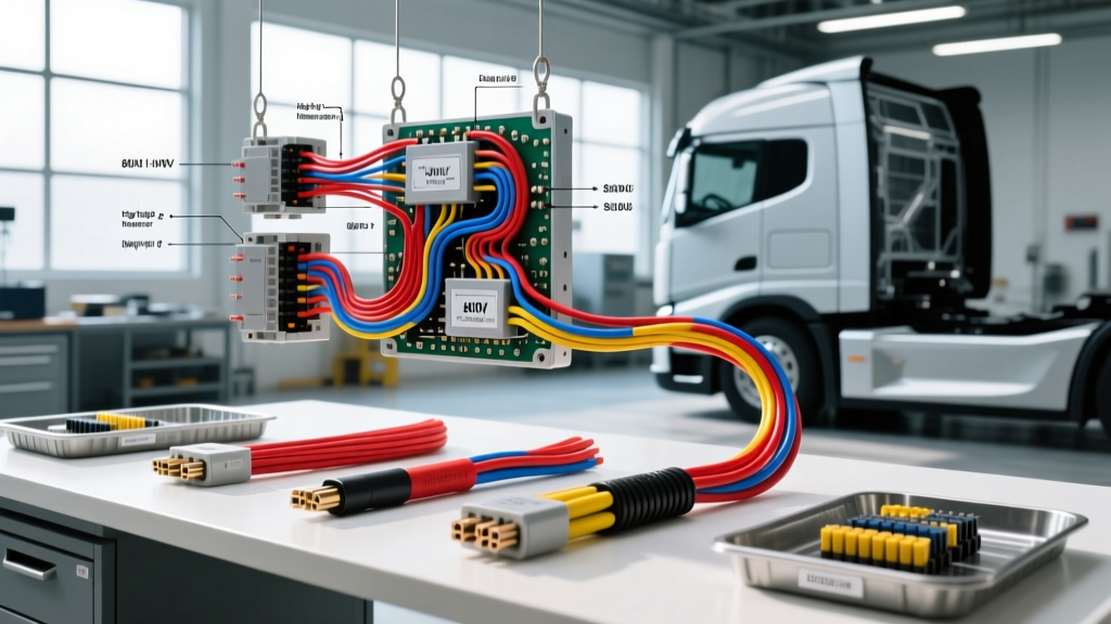
The Electrical Architecture Behind Slate Auto Electric Truck Startup Growth
The recent slate auto electric truck startup growth highlights a broader industry pivot toward modular, software-defined electric vehicle (EV) platforms. Unlike legacy OEMs burdened by decades of inherited 12V and 400V electrical architectures, modern EV truck startups are engineering their high-voltage (HV) power distribution networks from the ground up. This clean-sheet approach allows for the integration of 800V DC architectures, advanced battery management system (BMS) topologies, and modular wiring harnesses that reduce vehicle weight while increasing thermal efficiency.
For automotive electrical technicians and EV systems engineers, understanding the technical specifications driving this new wave of electric trucks is critical. This reference guide details the high-voltage cabling standards, connector pin configurations, High Voltage Interlock Loop (HVIL) protocols, and low-voltage CAN bus topologies that define the next generation of electric truck platforms.
High-Voltage (HV) Power Distribution: 800V vs. 400V Platforms
The cornerstone of modern EV truck architecture is the shift from 400V nominal systems to 800V nominal systems. By doubling the system voltage, startups can halve the current required for the same power output (Power = Voltage × Current). This reduction in current drastically decreases resistive heating (I²R losses) and allows for smaller, lighter gauge wiring between the battery pack, the main traction inverter, and the electric drive motors.
According to ISO 6722-1 standards for road vehicle single-core cables, HV cables must utilize specific cross-sectional areas to handle continuous and peak current loads while maintaining strict bend-radius tolerances. In an 800V electric truck platform, the main battery-to-inverter DC links typically operate at 400A continuous and up to 800A peak during hard acceleration or heavy towing.
HV Cable Sizing and Shielding Specifications
Automotive HV cables are universally mandated to feature an orange outer jacket (typically XLPE or silicone rubber) for immediate visual identification of shock hazards. Beneath the outer jacket, a braided copper or aluminum foil shield is required to prevent electromagnetic interference (EMI) from disrupting low-voltage telemetry and infotainment systems.
| Nominal Cross-Section | Approx. AWG Equivalent | Continuous Current Rating (800V) | Typical Application in EV Truck | Shielding Requirement |
|---|---|---|---|---|
| 35 mm² | 2 AWG | 180A | HVAC Compressor, DC-DC Converter | Braided Copper (≥85% coverage) |
| 50 mm² | 1/0 AWG | 250A | On-Board Charger (OBC), PTC Heater | Braided Copper + Aluminum Foil |
| 70 mm² | 2/0 AWG | 320A | Rear E-Axle Motor Inverter Feed | Braided Copper + Aluminum Foil |
| 95 mm² | 3/0 AWG | 400A | Main Battery Pack to Front Inverter | Double Braided Copper Shield |
When terminating these cables at the inverter or battery contactor busbars, technicians must use specialized hex-crimp or ultrasonic welding lugs. For M8 terminal bolts, the torque specification is typically 20 Nm ± 2 Nm, while M10 bolts require 40 Nm ± 3 Nm, verified with a calibrated torque wrench to prevent micro-arcing and subsequent thermal runaway.
Connector Pinouts and HVIL Safety Loops
To protect first responders and technicians, modern EV truck platforms utilize a High Voltage Interlock Loop (HVIL). The HVIL is a low-voltage (usually 5V or 12V) continuous circuit that passes through every HV connector in the powertrain. If any HV connector is unseated or a service disconnect is pulled, the HVIL circuit breaks, signaling the BMS to immediately open the main battery contactors and isolate the high-voltage pack.
Standard HV Connector Pin Configuration (2-Pin + HVIL)
Most modular EV truck platforms use shielded, quick-disconnect connectors (such as TE Connectivity H-MTD or Amphenol AT series) for auxiliary HV components like the electric power steering (EPS) pump or the electric air conditioning compressor.
- Pin A (HV+): Main DC Positive feed (Orange, 35mm² or 50mm² cable).
- Pin B (HV-): Main DC Negative return (Orange, 35mm² or 50mm² cable).
- Pin C (HVIL Out): Interlock signal output (Typically 18 AWG, Green or White wire).
- Pin D (HVIL In): Interlock signal return/ground (Typically 18 AWG, Green or White wire).
Diagnostic Note: When troubleshooting an "HV Isolation Fault" or "Interlock Open" diagnostic trouble code (DTC), technicians should use a digital multimeter (DMM) to measure the voltage drop across Pins C and D. A healthy, seated connector will show less than 50mV drop. An open circuit or high resistance (>5 ohms) indicates a pushed-out pin, a broken interlock wire, or a failed microswitch inside the connector housing.
DC Fast Charging Integration: NACS and CCS Topologies
A major factor accelerating slate auto electric truck startup growth is the adoption of standardized fast-charging protocols, heavily leaning toward the North American Charging Standard (NACS), now formalized under SAE J3400. Understanding the pinout of the vehicle-side charging receptacle is essential for diagnosing charge initiation failures.
NACS (J3400) DC Fast Charging Pinout Reference
| Pin Designation | Function | Wire Color / Gauge | Signal / Voltage Spec |
|---|---|---|---|
| DC+ (Pin 1) | Positive DC Fast Charge Feed | Orange / 95mm² (3/0 AWG) | Up to 1000V DC |
| DC- (Pin 2) | Negative DC Fast Charge Return | Orange / 95mm² (3/0 AWG) | Ground Reference |
| Proximity Pilot (PP) | Cable Connection Verification | Yellow / 18 AWG | Resistor network (150Ω - 1500Ω) |
| Control Pilot (CP) | PWM Communication with Charger | Blue / 18 AWG | ±12V PWM (1kHz) |
| Ground (PE) | Chassis / Protective Earth | Green-Yellow / 50mm² | 0V Reference |
If a truck fails to initiate a DC fast charge, the fault often lies in the Control Pilot (CP) circuit. The vehicle's charge controller expects a 1kHz PWM signal from the EVSE (charger). If the CP wire suffers from chafing or moisture ingress in the receptacle, the PWM duty cycle will be distorted, and the BMS will abort the charging sequence to prevent overcurrent events.
Low-Voltage CAN Bus and Telemetry Integration
While the high-voltage system propels the vehicle, the low-voltage (12V or 48V) architecture acts as the central nervous system. EV truck startups utilize high-speed Controller Area Network (CAN) buses to manage battery thermal conditioning, regenerative braking torque requests, and over-the-air (OTA) updates.
CAN Bus Physical Layer Specifications
- Topology: Linear Bus with 120-ohm terminating resistors at each extreme end of the network.
- Cabling: Shielded Twisted Pair (STP). CAN-High and CAN-Low must maintain a twist rate of at least 1 twist per inch to reject common-mode EMI generated by the 800V inverter switching frequencies.
- Voltage Levels (Recessive State): CAN-H ≈ 2.5V, CAN-L ≈ 2.5V.
- Voltage Levels (Dominant State): CAN-H ≈ 3.5V, CAN-L ≈ 1.5V.
Troubleshooting Tip: To verify CAN bus integrity without an oscilloscope, power down the vehicle completely (disconnect the 12V auxiliary battery and wait 5 minutes for modules to sleep). Set your DMM to measure resistance (Ohms) and probe between the CAN-H and CAN-L pins at the OBD-II diagnostic port (typically Pin 6 and Pin 14). A healthy network will read exactly 60 ohms (two 120-ohm resistors in parallel). A reading of 120 ohms indicates one missing terminator, while a reading near 0 ohms indicates a dead short between the CAN lines.
Diagnostic Procedures for HV Isolation Faults
An HV Isolation Fault occurs when the BMS detects that the high-voltage system is leaking current to the vehicle chassis. This is a critical safety failure that will immediately disable the vehicle. According to SAE J1766 safety guidelines, isolation must be maintained at a minimum of 500 ohms per volt of the maximum system voltage. For an 800V system, the minimum acceptable isolation resistance is 400 kΩ.
- Safety Prep: Don Category 0 arc-flash PPE and Class 0 (1000V) insulated gloves. Verify gloves with a visual and pneumatic roll test.
- De-Energize: Pull the Manual Service Disconnect (MSD) and wait 15 minutes for the inverter DC-link capacitors to bleed down.
- Verify Zero Voltage: Use a CAT III or CAT IV rated DMM to measure voltage between the HV+ and HV- busbars. Confirm 0V.
- Megger Test: Connect an Insulation Resistance Tester (Megger) set to 500V DC. Place the positive probe on the HV+ busbar and the negative probe on a clean, unpainted chassis ground.
- Interpret Results: A reading below 400 kΩ indicates a breach. Common culprits in electric trucks include coolant leaks inside the battery thermal management plates, chafed orange cabling near the suspension subframe, or failed ceramic capacitors inside the onboard charger.
Conclusion
The engineering agility seen in slate auto electric truck startup growth is fundamentally rooted in advanced electrical architecture. By leveraging 800V platforms, rigorously shielded HV cabling, and robust HVIL safety loops, these manufacturers are building trucks capable of immense towing capacity and rapid charging. For the automotive electrical specialist, mastering these specifications—from 95mm² DC link crimps to CAN bus termination diagnostics—is no longer optional; it is the baseline requirement for servicing the future of commercial and light-duty electric transport.