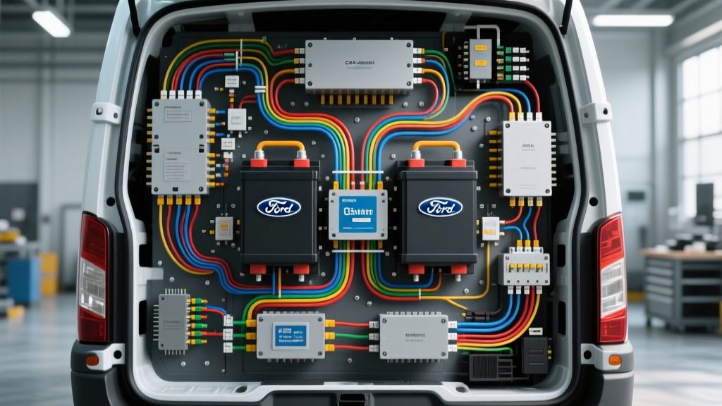
Introduction to Modern Transit Vans Auto Electric Architecture
When evaluating modern commercial vans auto electric architectures, the Ford Transit represents a significant leap from legacy 12-volt systems to highly complex, multiplexed CAN-bus and LIN-bus networks. Unlike older commercial vehicles where the alternator output was statically regulated to ~14.2V, modern Transit vans utilize a Smart Alternator controlled by the Powertrain Control Module (PCM). This system dynamically adjusts charging voltage between 12.5V and 15.0V based on real-time electrical load, battery state of charge (SoC), and fuel economy targets. For upfitters, van-lifers, and commercial fleet technicians, understanding this dynamic behavior is critical. Misinterpreting these voltage fluctuations as a failing alternator is a common diagnostic pitfall. This advanced technical guide explores the intricate wiring of the Battery Management System (BMS), dual-battery isolation via DC-DC charging, and the integration of auxiliary upfitter circuits without corrupting the vehicle's high-speed CAN-bus network.
Smart Alternator and Battery Management System (BMS)
The foundation of the Transit's electrical management is the BMS sensor, physically mounted on the negative battery cable's ground lug. This Hall-effect sensor continuously monitors current flow (amperage), voltage, and battery temperature. It communicates this data to the PCM via a Local Interconnect Network (LIN) bus. The PCM then dictates the alternator's internal voltage regulator via a Pulse Width Modulation (PWM) signal. If you are installing a secondary house battery or high-draw inverter, you must never bypass or relocate the BMS sensor. Doing so will trigger a U-code (e.g., U3000) and force the PCM into a fail-safe charging mode, potentially overcharging or undercharging your battery banks.
BMS Sensor Pinout and LIN-Bus Integration
The BMS sensor typically utilizes a 3-pin Deutsch DT or OEM weatherpack connector. When probing this circuit with an oscilloscope, the LIN-bus data line will show a 12V nominal square wave that drops to approximately 7V during active data transmission. Below is the standard pinout configuration for the 2015-2023 Ford Transit BMS sensor (Motorcraft part # SW-7182 or equivalent):
| Pin | Wire Color | Function | Signal Type / Specification |
|---|---|---|---|
| 1 | Violet/Orange (VT/O) | LIN Bus Data | Digital PWM (12V nominal, 7V low) |
| 2 | Black/Yellow (BK/Y) | Sensor Ground | Chassis Ground (< 0.05V drop) |
| 3 | White/Red (WH/R) | Reference Voltage | 12V+ (Hot at all times) |
Installation Note: When re-terminating the negative battery cable to accommodate a DC-DC charger ground, the BMS sensor must remain as close to the battery post as possible. The M8 nut securing the negative cable and BMS sensor to the chassis ground point must be torqued to exactly 12 Nm (106 lb-in) to prevent micro-arcing, which introduces electromagnetic interference (EMI) onto the LIN bus.
Dual-Battery Isolation and Upfitter Integration
Historically, dual-battery setups in commercial vans relied on a Voltage Sensitive Relay (VSR) or a simple continuous-duty solenoid. However, because the Transit's smart alternator frequently drops system voltage to 12.5V or 12.7V during cruising to reduce engine parasitic drag, a standard VSR will constantly disengage, failing to charge the secondary house battery. Furthermore, connecting a large secondary lithium (LiFePO4) battery bank directly to the factory alternator can cause an inrush current spike that exceeds the alternator's diode bridge rating, leading to catastrophic stator failure.
Wiring the DC-DC Battery Charger
The only reliable method for integrating a secondary battery bank in modern vans auto electric systems is via a microprocessor-controlled DC-DC charger (e.g., Victron Orion-Tr Smart 12/12-30 or Redarc BCDC1225D). These devices feature a 'Smart Alternator' detection wire that monitors the vehicle's ignition or CAN-bus activity to engage the charging cycle only when the engine is running and the PCM has commanded a high-voltage bulk charge phase.
AWG Sizing and Overcurrent Protection Chart
Proper wire gauge selection is paramount to prevent voltage drop and thermal events. The following specifications apply to a standard 30A DC-DC charger installation with a 15-foot cable run (positive and negative combined):
- Main Positive Feed (Starter to DC-DC): 4 AWG Stranded Copper (Class K fine-wire for vibration resistance).
- Main Negative Ground (DC-DC to Chassis): 4 AWG Stranded Copper, terminated with a closed-loop lug and sealed with adhesive-lined Mil-spec heat shrink.
- Primary Overcurrent Protection (Starter Battery side): 150A Mega Fuse or Class T Fuse, mounted within 7 inches of the positive battery terminal.
- Secondary Overcurrent Protection (DC-DC Input side): 40A ANL Fuse.
- House Battery Feed (DC-DC Output): 6 AWG Stranded Copper.
- House Battery Overcurrent Protection: 50A ANL Fuse.
- Ignition/Smart Alt Sense Wire: 18 AWG, tapped into the upfitter module or PCM ignition run/start circuit using a Posi-Tap connector (never use T-taps, which corrode and pierce the copper strands).
Upfitter Switch Module and Auxiliary Relay Wiring
Ford Transit vans equipped with the auxiliary upfitter switch package provide six dashboard-mounted switches, pre-wired to a relay module located under the driver's seat or behind the B-pillar. These circuits are powered by the battery and protected by individual fuses in the Body Control Module (BCM). When wiring high-draw accessories like LED light bars, air compressors, or hydraulic PTOs, it is vital to use the upfitter wires strictly as low-current trigger signals for external heavy-duty relays, rather than passing the full load through the factory harness.
Upfitter Pinout and Load Limits
The upfitter connector is typically a 12-pin or 16-pin OEM block. Below are the standard trigger wire colors and their respective factory fuse limits:
- Switch 1 (30A Capacity): Violet/White (VT/WH) - Ideal for heavy winch solenoids or main inverter triggers.
- Switch 2 (30A Capacity): Brown/White (BN/WH) - Ideal for high-amperage air compressor relays.
- Switch 3 (15A Capacity): Yellow/Black (YE/BK) - Suitable for auxiliary lighting contactors.
- Switch 4 (15A Capacity): Green/Orange (GN/O) - Suitable for interior lighting banks.
- Switch 5 (10A Capacity): Gray/Brown (GY/BN) - Low current logic triggers.
- Switch 6 (10A Capacity): Blue/White (BL/WH) - Low current logic triggers.
Expert Tip: If your accessory requires a continuous draw exceeding 20A, you must wire the upfitter trigger wire to the coil (pins 85/86) of an external 4-pin Bosch-style relay or a solid-state contactor. The relay's switched contacts (pins 30/87) should then be wired directly to the secondary battery bank via appropriately sized AWG cabling and an independent inline fuse.
Troubleshooting CAN-Bus Faults in Upfitted Vans
Aftermarket wiring modifications frequently introduce faults into the Transit's high-speed CAN-bus (HS-CAN) and medium-speed CAN-bus (MS-CAN) networks. Symptoms include erratic instrument cluster behavior, random battery drain, or the inability to crank the engine. When diagnosing these issues, rely on a digital storage oscilloscope (DSO) rather than a standard multimeter.
Diagnostic Decision Tree for Network Faults
- Symptom: U0129 (Lost Communication with Brake System Control Module).
Cause: Often caused by aftermarket trailer brake controllers splicing into the CAN-H or CAN-L wires near the OBDII port or kick panel.
Fix: Remove all aftermarket splices. Measure CAN-H (typically White/Blue) and CAN-L (typically White) resistance across the OBDII pins 6 and 14 with the battery disconnected. The resistance must read exactly 60 Ohms (two 120-Ohm terminating resistors in parallel). If it reads 120 Ohms, one terminator is missing or the bus is severed. - Symptom: U3000 (Control Module Failure) associated with the BMS.
Cause: EMI interference from poorly routed high-current inverter cables running parallel to the LIN-bus wire.
Fix: Reroute high-voltage DC cables at least 12 inches away from any CAN/LIN data lines. If they must cross, ensure they intersect at a strict 90-degree angle to minimize inductive coupling. - Symptom: Parasitic Draw exceeding 50mA after 20 minutes.
Cause: An aftermarket accessory (like a GPS tracker or dashcam) wired to a constant 12V source is preventing the BCM from entering 'sleep' mode.
Fix: Perform a voltage drop test across individual fuses in the BCM and Passenger Junction Box (PJB) using a milli-volt meter to isolate the circuit keeping the CAN-bus awake.
Authoritative References
For further technical validation and wiring schematics, consult the following authoritative resources:
- SAE J1113 Electromagnetic Compatibility Standards - Essential guidelines for routing data cables and mitigating EMI in commercial vehicle upfits.
- Ford Motorcraft Owner Manuals & Upfitter Guides - Official documentation for Transit upfitter switch pinouts, torque specifications, and BMS sensor requirements.
- etrailer.com Technical Articles - Practical application guides for DC-DC charger installations and heavy-duty relay wiring in commercial vans.