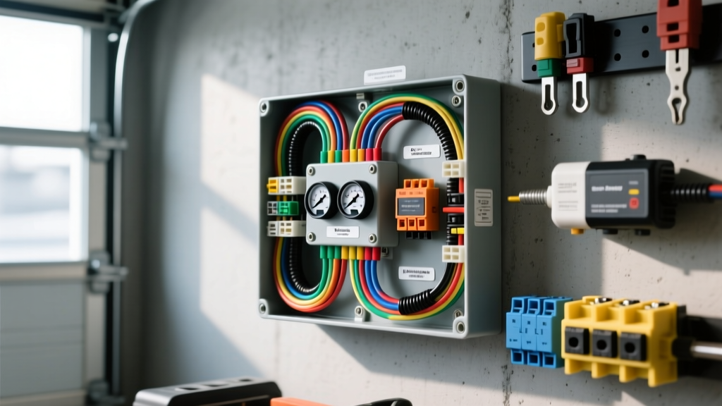
Introduction to Your Van's Auto Electric Architecture
Understanding the fundamentals of your van's auto electric system is the first step toward reliable diagnostics, successful upfitting, and avoiding costly wiring fires. Unlike standard passenger sedans, cargo and passenger vans (such as the Ford Transit, Ram ProMaster, and Chevy Express) feature extended wheelbases, heavy auxiliary loads, and complex multi-zone fuse panels. When you begin tracing circuits, you are not just looking at a simple battery-to-bulb loop; you are interacting with sophisticated multiplexed networks and high-amperage charging systems.
This beginner-friendly guide breaks down the core components of modern van electrical systems, providing you with the exact wire gauges, color codes, and diagnostic procedures used by professional technicians. Whether you are troubleshooting a no-crank condition or planning a dual-battery camper conversion, mastering these fundamentals is non-negotiable.
The Big Three: Battery, Alternator, and Smart Charging
At the heart of the van's auto electric network is the charging system. Older vehicles utilized simple 1-wire or internally regulated alternators. Modern vans, however, employ Smart Charge Systems managed by the Powertrain Control Module (PCM) to optimize fuel economy and battery longevity.
The Battery Management System (BMS) Shunt
Most modern vans feature a BMS sensor clamped directly onto the negative battery terminal. This shunt monitors current flow in and out of the battery to calculate the exact State of Charge (SOC) and State of Health (SOH). The PCM uses this data to command the alternator via a LIN (Local Interconnect Network) bus signal.
- Critical Rule: Never ground aftermarket accessories (like inverters or winches) to the negative battery terminal after the BMS shunt. Doing so bypasses the sensor, causing the PCM to miscalculate the battery's SOC, which can lead to severe overcharging or a dead battery.
- Proper Grounding: All heavy auxiliary grounds must be tied to the chassis ground stud or the engine block, bypassing the BMS shunt entirely.
Alternator Output and Connectors
Modern van alternators typically output between 210A and 250A to support factory HVAC, lighting, and telemetry. The electrical connector on the back of the alternator usually features a 3-pin plug:
- Pin 1 (LIN Bus): Data communication to the PCM.
- Pin 2 (Sense): Battery voltage sense wire (often routed directly to the B+ junction block).
- Pin 3 (Ignition/Enable): 12V+ wake-up signal from the ignition relay.
Wire Gauge (AWG) and SAE Color Coding Standards
Selecting the correct American Wire Gauge (AWG) is critical. Undersized wires in a van's long wheelbase runs will suffer from severe voltage drop, leading to dim lights, slow power windows, and melted insulation. According to SAE J1128 standards, primary wire must be rated for the specific amperage and ambient temperature of the engine bay.
| AWG Size | Max Amps (Chassis) | Common Van Application | Standard SAE Color Code |
|---|---|---|---|
| 1/0 AWG | 150A - 200A | Main battery grounds, starter B+ cable, heavy inverter feeds | Black (Ground) |
| 4 AWG | 80A - 100A | Alternator B+ output to junction block, auxiliary battery feeds | Red (Battery Power) |
| 8 AWG | 40A - 50A | Horn circuits, high-amperage cooling fan relays, trailer brake feeds | Dark Blue or Red |
| 12 AWG | 15A - 20A | Cigarette lighter sockets, interior dome lights, power window motors | Purple or Light Green |
| 16 AWG | 6A - 8A | Dash illumination, PCM sensor feeds, tail light circuits | Brown (Tail/Marker) |
| 18 AWG | 3A - 5A | CAN-bus data lines, low-current relay coils, LED marker lights | Yellow/Red Tracer |
Demystifying the Fuse Box and ISO Relays
The central junction box (CJB) in a van can contain upwards of 60 fuses and 15 relays. Understanding the standard ISO Mini Relay is the master key to unlocking 80% of all accessory and lighting diagnostics.
Standard 5-Pin ISO Relay Pinout
When looking at the bottom of a standard automotive relay, you will see five numbered terminals. Here is how they function in a typical van fuel pump or horn circuit:
- Pin 30 (Power In): Receives constant 12V+ from the battery via a high-amperage maxi-fuse.
- Pin 87 (Power Out): Sends 12V+ to the load (e.g., the fuel pump) when the relay is energized.
- Pin 86 (Coil Power): Receives 12V+ from the ignition switch or a control module to energize the internal electromagnet.
- Pin 85 (Coil Ground): Provides the ground path for the coil. In modern vans, the PCM often controls this ground side to activate the relay.
- Pin 87a (Normally Closed): Connected to Pin 30 when the relay is off. Rarely used in basic van circuits but common in alarm or dual-headlight systems.
Diagnostic Tip: If a van's cooling fan isn't running, use a multimeter to check for 12V at Pin 30 and a pulsing ground at Pin 85. If both are present but the fan doesn't run, the internal relay contacts are burned, or the load side (Pin 87) has an open circuit.
The Golden Rule: Voltage Drop Testing
Beginners often test for 12V at a connector, see 12V, and assume the circuit is healthy. This is a fatal diagnostic error. A single strand of corroded copper wire can carry 12V but will collapse under the amperage draw of a starter motor or headlight. The only accurate way to test high-current circuits in your van's auto electric system is the Voltage Drop Test.
Step-by-Step Starter Circuit Voltage Drop Test
According to ASE certification standards, a healthy 12V cranking circuit should never drop more than 0.5V total across the entire positive and negative sides.
- Preparation: Set your digital multimeter (DMM) to DC Volts. Ensure the van's battery is fully charged (minimum 12.4V resting). Disable the ignition or fuel pump so the engine cranks but does not start.
- Positive Side Test: Place the red DMM probe directly on the starter battery post (not the clamp). Place the black DMM probe directly on the starter B+ terminal. Have an assistant crank the engine. A reading above 0.2V indicates excessive resistance in the positive cable, the main fuse, or the junction block connections.
- Negative Side Test: Place the red DMM probe on the starter motor housing (clean bare metal). Place the black DMM probe on the negative battery post. Crank the engine. A reading above 0.1V indicates a poor engine-to-chassis ground strap or corrosion at the battery negative terminal.
- Connection Test: To isolate a bad connection, place one probe on the cable side of a connection and the other probe on the terminal side. Crank the engine. The drop across any single connection should not exceed 0.05V.
Common Van-Specific Electrical Failure Modes
Vans endure unique physical stresses that lead to specific electrical gremlins. Familiarize yourself with these common failure points to save hours of diagnostic time:
1. B-Pillar and Sliding Door Wiring Harness Chafing
The wiring loom that transitions from the van's main body into the sliding side door or rear barn doors is subjected to thousands of articulation cycles. Over time, the flexible rubber boot degrades, and the internal 16 AWG and 18 AWG wires (often controlling power locks, window motors, and CAN-bus lines) chafe against the metal bulkhead. Fix: Inspect the harness for brittle loom tape. Repair broken strands using solder-seal heat shrink connectors (never use twist-on crimp caps in high-flex zones) and wrap the new harness in split-loom corrugated tubing and friction tape.
2. Rear Chassis Ground Corrosion
Cargo vans frequently feature a main rear ground stud (often labeled G402 or similar in Ford Truck Body Builder manuals) located near the rear crossmember. This ground is responsible for the rear brake lights, license plate lamps, and rear ABS sensors. Because it is exposed to road spray and winter brine, it is highly prone to galvanic corrosion. Fix: Remove the ground bolt, wire-brush the chassis mating surface to bare metal, apply a dielectric grease coating to the ring terminal, and torque to factory specifications (usually 8-10 Nm for M6 ground studs).
3. Aftermarket Upfitter Relay Overload
Many vans feature an auxiliary upfitter fuse block under the hood. Beginners often wire high-draw accessories (like 100W LED light bars or air compressors) directly to the upfitter relay outputs without adding a secondary relay. This overloads the factory PCB traces. Fix: Use the factory upfitter circuit strictly as a low-amperage trigger (Pin 86/85) for a heavy-duty aftermarket 40A relay, pulling the main load current directly from the B+ junction block via an inline maxi-fuse.
Conclusion
Mastering your van's auto electric system requires moving beyond simple continuity checks and embracing systemic diagnostics. By respecting SAE wire gauge standards, understanding the nuances of smart charging BMS shunts, and religiously performing voltage drop tests, you will diagnose issues faster and build auxiliary systems that survive the harsh realities of the road. Keep your wiring diagrams handy, respect the CAN-bus networks, and always verify your grounds.