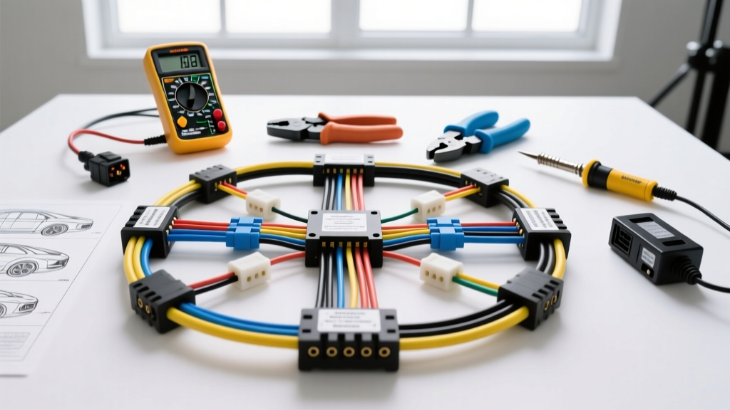
Building the Ultimate A to Z Mobile Auto Electrics Rig
When you are dispatched to a roadside callout or a customer's driveway, your vehicle is your entire workshop. Establishing a complete 'A to Z mobile auto electrics' setup requires more than just a digital multimeter and a box of crimp connectors. It demands a meticulously selected ecosystem of diagnostic hardware, mobile power delivery systems, and OEM-grade wiring repair components. In this comprehensive selection guide, we compare the essential tools and materials required to diagnose, repair, and verify complex automotive electrical systems in the field.
Core Diagnostic Modules: Oscilloscopes vs. Advanced Scanners
The cornerstone of any professional mobile auto electrical service is the ability to visualize voltage over time. While a standard multimeter can measure static voltage drop, it cannot capture the microsecond anomalies in a CAN bus network or a failing ignition coil dwell time. Below is a comparison of the primary diagnostic hubs for mobile technicians.
| Device | Type | Bandwidth / Specs | Best Mobile Application |
|---|---|---|---|
| PicoScope 4425A | Lab Scope | 4-Channel, 20 MHz, 200 MS/s | CAN bus decoding, parasitic draw, relative compression |
| Topdon Phoenix Lite | Tablet Scanner | 2-Channel Scope + Bi-Directional | Module coding, quick sensor waveform verification |
| Fluke 88V | Multimeter | 1000V DC, 10A Continuous, Min/Max | Voltage drop testing, alternator ripple, continuity |
For a true A to Z mobile auto electrics workflow, the PicoScope paired with a 60A DC current clamp is non-negotiable. It allows you to perform non-invasive parasitic draw tests by measuring the magnetic field around the negative battery cable, avoiding the risk of blowing your multimeter's internal fuse when a vehicle's modules wake up on the network.
The Wiring Repair Arsenal: Connectors, AWG, and Terminals
A mobile electrical repair is only as reliable as the splice. Twisting wires and wrapping them in electrical tape is a guaranteed callback. A professional A to Z mobile auto electrics kit must include OEM-style sealed connectors and cross-linked wiring.
Wire Insulation Selection: GXL vs. TXL
According to SAE J1128 standards, under-hood wiring requires high-temperature resistance. Always stock GXL (Cross-linked) wire over standard PVC or TXL. GXL features a thinner wall but withstands continuous temperatures up to 125°C, making it ideal for tight engine bay harness repairs where space and heat are primary concerns.
Deutsch DT and DTM Connector Specs
For sensor and actuator repairs, sealed connectors are mandatory. The Deutsch DT series is the industry standard for heavy-duty and automotive applications.
- Size 16 Pins: Accepts 14-18 AWG wire. Rated for 13A continuous. Ideal for oxygen sensors, MAP sensors, and injector circuits. (Wire colors typically: Signal = Gray/White, 5V Ref = Red/Black, Ground = Black).
- Size 12 Pins: Accepts 10-14 AWG wire. Rated for 20A continuous. Used for cooling fans, fuel pumps, and EGR valves.
Always use a calibrated ratcheting crimp tool to ensure the wire barrel and insulation barrel are compressed to exact specifications, followed by inserting the secondary wedge lock and applying heat-shrink boots over the rear silicone seal.
Aftermarket Accessory Integration: AWG and Relay Selection
A significant portion of mobile auto electrical work involves installing auxiliary lighting, winches, and high-draw audio equipment. Selecting the correct wire gauge and relay configuration is critical to prevent voltage drop and fire hazards.
Wire Gauge Sizing for High-Current Accessories
When routing power from the battery to the rear of a truck for a winch or auxiliary battery, voltage drop over distance dictates the AWG size, not just the amperage draw.
- 8 AWG OFC (Oxygen-Free Copper): Rated for ~50A over 10 feet. Ideal for dual-battery isolators and heavy-duty lighting relays.
- 4 AWG Welding Cable: Rated for ~150A over 15 feet. Mandatory for 12,000lb winches and high-output alternator upgrades (e.g., upgrading from a 105A to a 250A alternator requires upgrading the main charge wire from 6 AWG to 2/0 AWG).
Always use a mega fuse or ANL fuse within 18 inches of the battery positive terminal to protect the main feed wire in the event of a dead short.
Field Troubleshooting: Alternators and Starter Circuits
Mobile callouts frequently involve no-start or no-charge conditions. Understanding the specific pinouts of common alternators and starters is critical for rapid diagnosis.
GM CS130 Alternator 4-Pin Connector
A common mobile repair involves the GM CS130 alternator. If the alternator is not charging, technicians often mistakenly replace the unit without checking the exciter circuit. The 4-pin connector breakdown is as follows:
- Terminal L (Brown, 18 AWG): Lamp/Turn-on signal from the PCM or ignition switch. Requires 12V to excite the voltage regulator.
- Terminal S (Red, 14 AWG): Battery Sense. Must be routed directly to the battery positive or main fuse block to measure actual system voltage.
- Terminal F & P: Frequency and Phase outputs for PCM load management (often unused in older swaps).
If Terminal S reads 0V due to a broken sense wire, the alternator will default to a limp-home mode (usually ~13.2V) or shut off completely to prevent overcharging a phantom short.
Starter Solenoid Trigger Circuits
When a vehicle cranks slowly or not at all, perform a voltage drop test on the starter control circuit. The trigger wire (often Purple on GM, or Yellow/Light Green on Ford) is typically 12 or 14 AWG. Connect your multimeter's red lead to the starter solenoid 'S' terminal and the black lead to the battery negative post. Crank the engine. A reading above 0.5V indicates excessive resistance in the ignition switch, neutral safety switch, or starter relay contacts. Refer to Haynes Automotive Wiring Basics for specific vehicle routing diagrams.
Parasitic Draw Testing in the Field
Parasitic draws are a staple of mobile diagnostics. The acceptable sleep-mode draw for modern vehicles with multiple CAN modules is typically between 30mA and 50mA. To test this without breaking the circuit (which can wake up the modules):
- Connect a DC current clamp around the negative battery cable.
- Set your oscilloscope or advanced multimeter to the mV or low-amp DC setting.
- Close all doors, latch the hood, and lock the vehicle.
- Wait for the modules to enter sleep mode (can take up to 20 minutes on late-model European vehicles).
- If the draw remains above 50mA, begin pulling fuses one by one while monitoring the scope to identify the offending circuit.
Mobile Power Delivery: Lithium vs. Lead-Acid Jump Packs
To test starter circuits and alternator ripple, the vehicle's battery must be fully charged. Modern mobile auto electricians have largely transitioned from heavy lead-acid jump boxes to Lithium-Iron-Phosphate (LiFePO4) packs.
| Feature | Lead-Acid Jump Box (e.g., Clore JNC660) | LiFePO4 Pack (e.g., NOCO GB150) |
|---|---|---|
| Weight | ~18 lbs | ~1.5 lbs |
| Peak Amps | 1700A | 3000A |
| Memory Effect | High (requires constant trickle charge) | None (holds charge for months) |
| Mobile Suitability | Low (heavy, sulfates if neglected) | High (compact, USB-C rechargeable) |
For an A to Z mobile auto electrics rig, the LiFePO4 pack is superior. It can be kept in the diagnostic bag and used not just for jumping, but as a stable 12V power source to maintain module memory when replacing a vehicle's main battery.
Conclusion
Mastering A to Z mobile auto electrics requires shifting from a parts-swapper mentality to a circuit-analyzer mindset. By investing in a 4-channel oscilloscope, stocking SAE J1128 compliant GXL wire and sealed Deutsch connectors, and utilizing modern LiFePO4 power delivery, your mobile service can rival any brick-and-mortar dealership. For further reading on advanced module communication networks and OEM repair procedures, consult Delphi Technologies technical service bulletins.