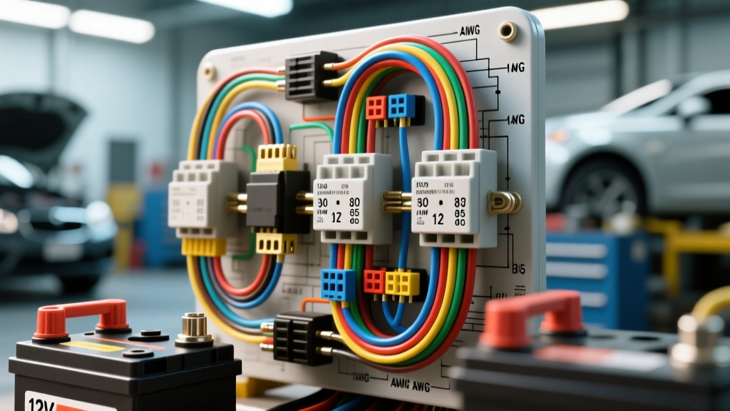
Demystifying the 12V Automotive Architecture
When approaching car electrical systems, beginners often feel overwhelmed by the maze of wires, connectors, and control modules hidden behind dashboards and within engine bays. However, beneath the complexity of modern CAN-bus networks lies a surprisingly straightforward foundation. Unlike household alternating current (AC) which operates at 120V or 240V, automotive networks rely on a 12-volt direct current (DC) architecture. In almost all modern vehicles, this is a 'negative-ground' system, meaning the vehicle's steel chassis and engine block serve as the common return path to the battery's negative terminal.
Understanding this fundamental concept is the first step toward mastering automotive wiring. By treating the chassis as a giant wire, manufacturers save miles of copper and reduce vehicle weight. For the DIY enthusiast or beginner technician, recognizing that every electrical component must have a clean, unimpeded path to both the positive power source and the negative chassis ground is the key to diagnosing 90% of all electrical faults.
The 'Big Three' Power Components
Every conventional internal combustion vehicle relies on three primary components to generate, store, and deploy electrical energy. Understanding their specific roles and failure modes is critical.
1. The Battery (Storage)
The battery is the chemical reservoir of your car electrical systems. It provides the massive surge of Cold Cranking Amps (CCA) required to spin the starter motor, and it acts as a giant capacitor to smooth out voltage spikes from the alternator. A fully charged lead-acid automotive battery rests at roughly 12.6V. If your resting voltage drops below 12.4V, the battery is only 75% charged, which can lead to sluggish cranking and premature failure of the battery plates due to sulfation.
2. The Alternator (Generation)
Once the engine is running, the alternator takes over. It is essentially a three-phase AC generator equipped with an internal diode trio (rectifier) that converts the alternating current into the 12V DC required by the vehicle. A healthy alternator will output between 13.8V and 14.4V at idle. If you see voltages exceeding 14.8V, your internal voltage regulator has likely failed, which will boil the battery acid and fry sensitive electronic control units (ECUs).
3. The Starter Motor (Deployment)
The starter is the most electrically demanding component in the vehicle, often drawing between 150 and 350 amps during the initial cranking phase. Because of this massive current draw, the starter circuit requires heavy-gauge wiring and robust, clean connections to prevent severe voltage drop.
Automotive Wire Sizing and Insulation Standards
One of the most common beginner mistakes in car electrical systems is using residential THHN solid-core wire. Household wire is designed to be pulled through PVC conduit in a climate-controlled wall; it will quickly fail in an engine bay due to vibration, heat, and exposure to petroleum products. Automotive wiring must comply with standards like SAE J1128, which dictates the use of stranded copper with specialized insulation.
For modern engine bays, you should exclusively use GXL (General Cross-Linked) or TXL (Thin-wall Cross-Linked) wire. These feature a cross-linked polyethylene insulation that resists melting up to 155°C (311°F) and withstands direct contact with hot exhaust manifolds.
Standard AWG Sizing Chart for Automotive Applications
| AWG Size | Max Ampacity (Continuous) | Common Automotive Application | Terminal Type |
|---|---|---|---|
| 18 AWG | 10 Amps | LED lighting, dashboard illumination, sensor signals | 1.5mm / 16-14 AWG crimp |
| 14 AWG | 20 Amps | Headlights, horn circuits, fuel pump power | 2.5mm / 14-12 AWG crimp |
| 12 AWG | 30 Amps | Power windows, aftermarket amplifiers, radiator fans | 4.0mm / 12-10 AWG crimp |
| 8 AWG | 50 Amps | Main accessory power feeds, high-draw winches | Ring terminal, 5/16 inch stud |
| 4 AWG | 120 Amps | Alternator output, starter motor positive cable | Ring terminal, 3/8 or 5/16 inch stud |
| 1/0 AWG | 250+ Amps | Heavy-duty battery cables, chassis grounding straps | Heavy-duty ring terminal, 1/2 inch stud |
For an excellent deep-dive into wire selection and circuit protection, the educational resources at AutoShop 101 provide fantastic visual breakdowns of how wire resistance increases over distance, requiring you to step up your AWG size for long runs (such as routing power to a trailer hitch).
Understanding ISO Mini Relays and Pinouts
Relays are the unsung heroes of car electrical systems. They allow a low-amperage switch (like the delicate headlight stalk on your steering column) to safely control a high-amperage load (like a pair of 55W halogen headlights) without melting the switch contacts. The most ubiquitous relay in automotive history is the standard ISO Mini Relay, often referred to as a 'Bosch-style' relay.
Beginners must memorize the standard 5-pin ISO layout to troubleshoot effectively:
- Pin 30 (Common): The main high-amperage 12V+ power input from the battery (always protected by a fuse).
- Pin 87 (Normally Open): The high-amperage 12V+ output that goes to the accessory (e.g., the fuel pump). Power flows from 30 to 87 only when the relay is energized.
- Pin 87a (Normally Closed): Outputs power when the relay is off. Often unused in standard automotive wiring but vital for specific alarm or security circuits.
- Pin 86 (Coil Power): Receives the low-amperage 12V+ trigger signal from the dashboard switch or ECU.
- Pin 85 (Coil Ground): The ground path for the electromagnetic coil. When the circuit between 86 and 85 is completed, the coil magnetizes and pulls the internal switch, connecting 30 to 87.
Pro-Tip: When wiring aftermarket accessories like off-road light bars or air compressors, always use a relay harness. Running 20 amps of current through an auxiliary toggle switch on your dashboard will eventually cause the switch to melt and catch fire.
The Art of the Ground and Voltage Drop Testing
If there is one golden rule in automotive diagnostics, it is this: Always check the ground first. Because the vehicle chassis is used as the return path, any rust, paint, undercoating, or loose hardware at a grounding point will introduce electrical resistance. Resistance creates heat and starves the component of voltage.
Beginners often rely on a multimeter's continuity beep or a basic 12V test light to verify a circuit. This is a critical error. A single strand of copper wire can carry enough current to light a test light or trigger a continuity beep, but it will instantly collapse under the load of a real automotive component. The only accurate way to diagnose car electrical systems is by performing a Voltage Drop Test.
How to Perform a Voltage Drop Test
- Set your digital multimeter to DC Volts.
- Ensure the circuit is under load and active (e.g., the engine is cranking, or the cooling fan is spinning).
- Place your red multimeter probe on the positive battery post (not the clamp, the actual lead post).
- Place your black multimeter probe on the positive terminal of the component you are testing (e.g., the starter solenoid stud).
- Read the voltage. The multimeter is now measuring the difference in potential (the voltage 'lost' to resistance in the cable).
Acceptable Thresholds: According to Bosch Mobility Solutions and general OEM standards, the maximum allowable voltage drop on a 12V cranking circuit is 0.10V per connection, and no more than 0.50V total for the entire positive cable run. If your meter reads 1.2V during cranking, you have a corroded battery clamp or a failing internal cable strand, regardless of what a test light might tell you.
Common Beginner Wiring Mistakes to Avoid
- Using Solder on High-Vibration Connections: While soldering seems secure, it creates a rigid, brittle joint. In the high-vibration environment of an engine bay, soldered wire joints will quickly suffer from metal fatigue and snap. Always use high-quality open-barrel or closed-barrel crimps with heat-shrink adhesive seals.
- Twist-and-Tape Splices: Electrical tape degrades rapidly under hood temperatures, unraveling and exposing bare copper to moisture and short circuits. Always use heat-shrink butt connectors with an integrated polyamide adhesive lining.
- Ignoring DIN Color Codes: While aftermarket kits use random colors, European and many global manufacturers follow DIN 72551-6 color codes. For example, Brown is almost universally chassis ground, Black is often switched power, and Red is direct battery power. Adhering to these standards makes future troubleshooting infinitely easier.
Mastering car electrical systems does not require an engineering degree. By respecting the 12V architecture, utilizing SAE-rated GXL wiring, properly deploying ISO relays, and relying on voltage drop testing rather than guesswork, you will build robust, reliable circuits that stand the test of time and the rigors of the open road.