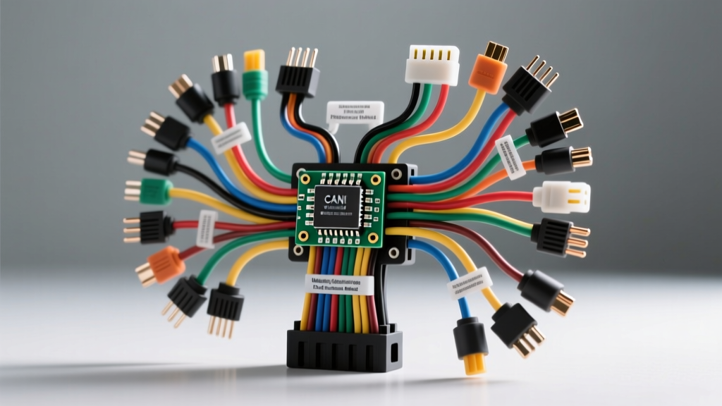
The Flaw in Traditional Ammeter Testing
When diagnosing a dead battery or excessive parasitic draw, the traditional method of disconnecting the negative battery terminal and inserting a digital multimeter (DMM) in series is fundamentally flawed for modern vehicles. Modern automotive electrical architectures rely on complex Controller Area Network (CAN) bus systems and gateway modules. When you break the circuit to insert an ammeter, the sudden voltage drop and subsequent reconnection simulate a door-ajar or ignition-on event. This wakes up the Body Control Module (BCM) or Junction Box Electronics (JBE), forcing the entire CAN bus into a dominant state. Instead of measuring the true sleep-state draw (typically 20mA to 50mA), you will read a massive 2A to 5A draw, leading technicians down a diagnostic rabbit hole of pulling fuses and unnecessarily replacing modules.
The Chris Auto Electrical Voltage Drop Protocol
The Chris Auto Electrical method eliminates circuit interruption by utilizing non-intrusive voltage drop testing across fuses. By measuring the millivolt (mV) drop across the test points on the top of the fuses while the circuit remains closed, technicians can calculate the exact amperage flowing through that specific circuit without waking the gateway modules. This requires a high-resolution DMM capable of reading down to 0.1mV and a thorough understanding of fuse metallurgy and resistance characteristics.
Before beginning any parasitic draw test, baseline electrical integrity must be verified. Battery terminal torque specifications are critical; a loose 4 AWG main ground cable will introduce phantom voltage drops. Top-post lead-acid battery terminals should be torqued to 5-7 Nm (44-62 in-lbs), while GM-style side-terminal connections require exactly 11 Nm (95 in-lbs) to prevent micro-arcing that can mimic a parasitic draw.
Fuse Millivolt Drop Reference Chart
Because different fuse types utilize varying lengths and cross-sectional areas of zinc or copper alloy, their resistance profiles differ drastically. The chart below outlines the expected voltage drop for common automotive fuses. Note that these values assume a fully seated fuse with clean, oxidation-free female receptacle terminals.
| Fuse Type | Typical Resistance (mΩ) | 100mA Drop (mV) | 500mA Drop (mV) | 1A Drop (mV) |
|---|---|---|---|---|
| Micro2 | 12.5 - 15.0 | 1.2 - 1.5 | 6.2 - 7.5 | 12.5 - 15.0 |
| Low Profile Mini | 8.0 - 10.5 | 0.8 - 1.0 | 4.0 - 5.2 | 8.0 - 10.5 |
| Standard Mini | 6.5 - 8.0 | 0.6 - 0.8 | 3.2 - 4.0 | 6.5 - 8.0 |
| Standard ATO | 4.0 - 5.5 | 0.4 - 0.5 | 2.0 - 2.7 | 4.0 - 5.5 |
| JCase (20A-60A) | 1.5 - 2.5 | 0.1 - 0.2 | 0.7 - 1.2 | 1.5 - 2.5 |
Source: Derived from AutoShop 101 Electrical Training and OEM service manual specifications.
Managing CAN Bus Sleep States and Module Topology
To accurately measure parasitic draw, the vehicle's CAN bus must be allowed to enter its recessive 'sleep' state. This process, known as module timeout, can take anywhere from 15 to 45 minutes after the ignition is turned off and all doors are locked. During this time, modules perform memory writes, complete self-tests, and gradually power down internal voltage regulators.
The physical layer of the high-speed CAN bus (ISO 11898-2) utilizes a twisted pair of unshielded wires, typically 22 AWG (0.35 mm²). The twisting is critical, as it cancels out electromagnetic interference (EMI) from high-current ignition coils and alternator ripple. In most North American vehicles, CAN High (CAN H) is wired in Orange with a Black tracer, while CAN Low (CAN L) is Orange with a Brown tracer, though European platforms frequently use Yellow/Green pairings.
OBD-II DLC Pinout and CAN Bus Voltage Signatures
Monitoring the Data Link Connector (DLC) is the most efficient way to verify bus sleep states without back-probing delicate module connectors. Using a dual-trace oscilloscope or a high-speed DMM, monitor the following pins on the 16-pin OBD-II port:
| DLC Pin | Function | Wake State (Dominant) | Sleep State (Recessive/Off) |
|---|---|---|---|
| 4 | Chassis Ground | 0.00V | 0.00V |
| 5 | Signal Ground | 0.00V | 0.00V |
| 6 | CAN High (HS-CAN) | 2.5V to 3.5V | 0.0V (or 2.5V bias) |
| 14 | CAN Low (HS-CAN) | 2.5V to 1.5V | 0.0V (or 2.5V bias) |
| 16 | Battery Positive (B+) | 12.2V - 12.6V | 12.2V - 12.6V |
For deeper architectural insights, refer to the SAE J1939 CAN Bus Standards documentation regarding network layer timeouts.
OEM-Specific CAN Bus Variations: GM and Ford
Advanced diagnostics require recognizing that not all networks follow the standard ISO 11898 high-speed topology. General Motors utilizes a Single Wire CAN (SW-CAN) network, often referred to as GMLAN, for low-speed body control functions (e.g., seat memory, HVAC, infotainment). SW-CAN operates on DLC Pin 1, utilizing a single 18 AWG wire (typically Dark Green). Unlike the 120-ohm termination of a dual-wire bus, SW-CAN relies on an 88-ohm termination resistor network. If a GM vehicle exhibits a parasitic draw on the body bus, technicians must look for a short to voltage on the single wire, which will force all GMLAN modules into a high-voltage wake state (typically 4V).
Ford, conversely, employs a Medium-Speed CAN (MS-CAN) for body and instrument cluster communications, accessible on DLC Pins 3 (CAN H) and 11 (CAN L). The MS-CAN bus operates at a lower baud rate (125 kbps compared to the 500 kbps of the HS-CAN) and features a unique fault-tolerant architecture. If the CAN H wire chafes and shorts to ground, the MS-CAN bus will not crash; instead, it will switch to a single-wire operational mode. However, this fault-tolerant state prevents the gateway module from commanding a full network sleep, resulting in a persistent 300mA to 800mA parasitic draw. Diagnosing this requires measuring the termination resistance across Pins 3 and 11 with the battery disconnected; a reading of 60 ohms indicates healthy 120-ohm parallel terminators, while 120 ohms indicates an open circuit in one of the bus branches.
Advanced Module Isolation Techniques
Once a specific circuit is identified via the fuse voltage drop method, isolating the exact failing component requires precision. Never unplug a module connector while the circuit is live, as the inductive kickback from solenoids or the sudden loss of a termination resistor can corrupt module EEPROM data or trigger secondary bus faults.
Instead, utilize the 'voltage drop on the B+ feed' technique. If the fuse voltage drop indicates a 400mA draw on a circuit protected by a 15A ATO fuse, locate the physical wiring harness routing to the suspected modules. Using a specialized low-amp clamp meter (such as the CTi-400) or by measuring the millivolt drop across a known length of the 16 AWG or 18 AWG B+ supply wire, you can pinpoint exactly which branch of the harness is consuming the current. Furthermore, deploying a high-sensitivity thermal imaging camera (capable of detecting 0.05°C temperature differentials) over the exposed fuse box and module housings will instantly reveal internal voltage regulator failures or shorted CAN transceiver chips, which manifest as localized hot spots even at low milliamp draws.
By adopting the Chris Auto Electrical methodology—prioritizing non-intrusive testing, respecting CAN bus sleep timeouts, and leveraging OEM-specific network topologies—technicians can accurately diagnose parasitic draws on the first attempt, preserving module integrity and eliminating the guesswork associated with modern automotive electrical systems. For foundational electrical theory and advanced oscilloscope waveform libraries, the Bosch Mobility Solutions technical archive remains an indispensable resource for any serious auto electrician.