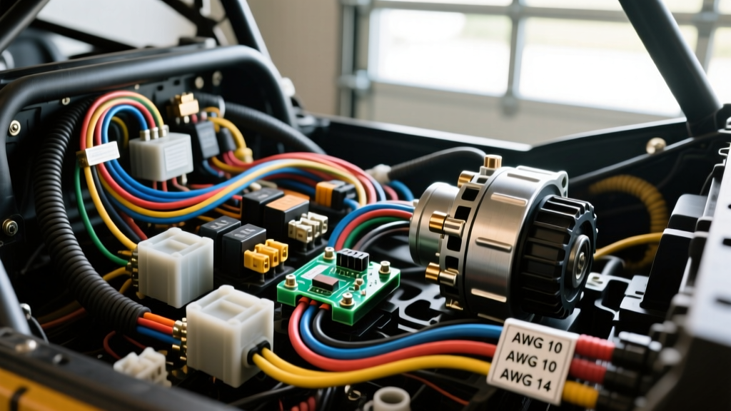
Architecting a Reliable Baja Auto Electric System
Executing a comprehensive baja auto electric upgrade is the difference between finishing a grueling off-road race and walking back to camp in the dark. Off-road buggies, sand rails, and VW Baja Bugs subject electrical components to extreme vibration, high ambient temperatures, and massive amperage spikes from modern accessories. Stock wiring harnesses, typically designed for low-draw factory lighting and basic ignition, simply cannot survive the punishing environment of desert racing or deep mud bogging. The PVC insulation becomes brittle, low-strand-count copper fractures under chassis flex, and undersized alternators overheat trying to power 300-watt LED light bars and 12,000-lb winches.
To build a truly resilient off-road electrical architecture, you must abandon the concept of daisy-chaining accessories. A professional-grade baja auto electric system relies on a centralized power distribution model, high-strand-count marine-grade wiring, vibration-proof connectors, and heavy-duty isolation solenoids. This guide details the exact specifications, wire gauges, and relay logic required to overhaul your buggy's electrical system from the alternator output to the auxiliary lighting circuits.
Core Power Generation: The Alternator Upgrade
Most vintage buggies and entry-level kit cars rely on outdated 45-amp to 65-amp generators or early externally regulated alternators. When you add a 150-amp electric fuel pump, dual cooling fans, and off-road lighting, these units fail rapidly. The industry standard for off-road upgrades is adapting a GM 12SI internally regulated alternator, typically rated at 105 to 140 amps.
GM 12SI 1-Wire Conversion and Sense Wiring
The GM 12SI is favored for its robust internal voltage regulator and simple adaptation. However, the '1-wire' configuration is frequently misunderstood in off-road builds. The alternator features three main connection points: the main BAT output post, Terminal #1 (Exciter), and Terminal #2 (Voltage Sense).
- Main BAT Post: Connect a SAE J1128 compliant 4 AWG high-strand-count welding cable directly to the starter solenoid or primary battery positive post. Protect this circuit with a 150A ANL fuse mounted within 18 inches of the battery.
- Terminal #2 (Sense): In a high-vibration buggy, running the sense wire directly to the BAT post on the alternator causes the regulator to compensate for voltage drop across the charge wire, leading to overcharging at the battery. Instead, run a dedicated 10 AWG red primary wire from Terminal #2 directly to the main positive busbar or battery post.
- Terminal #1 (Exciter): Jump Terminal #1 to Terminal #2, or run it through a dash-mounted ignition-switched 10A circuit with a 12V indicator bulb to provide the initial excitation current required for the alternator to begin charging at low RPMs.
When fabricating the alternator bracket, use 3/8-inch Grade 8 hardware with nylon-insert locknuts. Torque the mounting bolts to 25 lb-ft to prevent bracket fatigue and belt misalignment, which is a common failure point in high-RPM off-road engines.
Wire Gauge Selection and Voltage Drop Management
Off-road vehicles experience significant voltage drop due to long wire runs from rear-mounted engines to front-mounted batteries and fuse blocks. Using standard automotive wire charts will result in undersized cables. You must calculate wire size based on the total round-trip distance (positive and ground) and the maximum continuous amperage draw.
| AWG Size | Max Continuous Amps | Max Length (10ft Round Trip) | Max Length (20ft Round Trip) | Typical Buggy Application |
|---|---|---|---|---|
| 2 AWG | 150A | 12 ft | 6 ft | Alternator Main Charge, Battery to Starter |
| 4 AWG | 100A | 18 ft | 9 ft | Alternator to Front Busbar, Winch Power |
| 8 AWG | 50A | 25 ft | 12 ft | Main Feed to Auxiliary Fuse Block |
| 10 AWG | 30A | 30 ft | 15 ft | LED Light Bar Power, Cooling Fan Relays |
| 14 AWG | 15A | 40 ft | 20 ft | Relay Control Circuits, Dash Switches |
Note: Always use high-strand-count copper wire (e.g., TXL or GXL cross-linked polyethylene insulation) which resists engine bay heat up to 125°C, vastly outperforming standard PVC wire.
Relay Logic for High-Draw Off-Road Lighting
Running high-amperage LED light bars or HID rally lights through a dashboard toggle switch is a fire hazard and guarantees severe voltage drop at the light housing. You must use heavy-duty ISO mini relays (Bosch-style 4-pin or 5-pin) to handle the load. According to the Bosch Automotive Electrics Handbook, isolating the high-current load from the low-current switch circuit preserves switch life and ensures maximum voltage reaches the lights.
Standard ISO 4-Pin Relay Pinout
- Pin 30 (Common Input): 10 AWG Red wire from the fused auxiliary battery positive.
- Pin 87 (Normally Open Output): 10 AWG Red wire running to the LED light bar positive terminal.
- Pin 85 (Coil Ground): 14 AWG Black wire terminated to a dedicated chassis ground point.
- Pin 86 (Coil Power): 14 AWG Blue wire running to the dash-mounted toggle switch.
By wiring the system this way, the dashboard switch only carries the minimal amperage required to energize the relay coil (typically under 200mA), while the heavy 10 AWG wiring handles the 20A+ load of the light bar directly from the power source.
Dual Battery Isolation and Solenoid Wiring
In extreme baja auto electric builds, a single battery is insufficient to crank a high-compression engine while simultaneously powering a 12,000-lb winch and auxiliary lighting. The solution is a dual-battery setup separated by a continuous-duty solenoid, such as the Cole Hersee 24059. Unlike standard starter solenoids designed for 30-second duty cycles, continuous-duty solenoids can remain energized for hours without the coil melting.
Wire the primary Group 34 AGM battery to the engine starter and ECU. Wire a secondary deep-cycle battery to the auxiliary fuse block, winch, and lighting relays. Connect the positive posts of both batteries through the continuous-duty solenoid. Energize the solenoid coil via an ignition-switched circuit so the batteries parallel and charge together while the engine is running, but isolate automatically when the key is off, preventing your lighting system from draining your cranking battery.
Vibration-Proof Connectors and Grounding Strategy
The number one cause of electrical failure in off-road racing is poor grounding and connector fatigue. Standard ring terminals and plastic butt-splices will vibrate loose or crack within a few hundred miles of washboard dirt roads.
Deutsch DT Series Connectors
For all removable off-road accessories (light bars, roof racks, external fuel pumps), use Deutsch DT series connectors. These utilize solid copper, nickel-plated crimp pins and feature silicone rear grommets that seal the wire entry points against water and dust intrusion. Always use a dedicated ratcheting crimp tool (never pliers) to compress the wire barrel, and apply adhesive-lined dual-wall heat shrink over the rear boot for mechanical strain relief.
Star Washers and Chassis Grounding
When terminating ground wires to the chassis, never use standard split-ring lock washers. The constant harmonic vibration of a tube chassis will cause split washers to flatten and lose tension. Instead, use internal-tooth star washers sandwiched between the ring terminal and the bare chassis metal. Scrape away all powder coat, paint, and primer down to bare steel using a wire wheel, apply the star washer to bite into the metal, torque the bolt, and then seal the entire connection with liquid electrical tape or marine-grade anti-corrosion grease to prevent galvanic corrosion.
Final System Validation
Once the baja auto electric architecture is assembled, perform a voltage drop test across the main charge cable and all primary ground straps while the engine is under load (RPMs held at 2,500 with all lights and fans engaged). A healthy system should show no more than a 0.2V drop across any single cable or connection. By adhering to heavy-duty AWG sizing, continuous-duty isolation, and vibration-resistant termination methods, your off-road vehicle will maintain rock-solid electrical reliability in the harshest environments on earth.