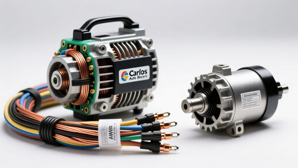
Introduction to Auto Electric Component Selection
When modern vehicle electrical systems demand more amperage than factory specifications can provide, technicians and enthusiasts face a critical sourcing decision. The debate often centers on specialized remanufactured suppliers versus standard original equipment manufacturer (OEM) replacements. In this comprehensive product comparison and selection guide, we evaluate Carlos Auto Electric high-output charging and cranking components against standard big-box auto parts store alternatives and OEM units. Whether you are wiring a high-amperage car audio system, supporting auxiliary off-road lighting, or simply restoring a classic vehicle's marginal charging system, understanding the internal architecture and external wiring requirements of your chosen components is paramount.
Carlos Auto Electric vs. Big-Box Remanufactured Units
Standard 'white-box' remanufactured alternators found at local auto parts chains typically reuse the original stator and rotor, simply replacing the voltage regulator, brushes, and bearings. While adequate for stock applications, these units often fail to meet the demands of modern accessory loads. Conversely, specialized suppliers like Carlos Auto Electric frequently upgrade the internal architecture during the remanufacturing process.
Stator Architecture: Round Wire vs. Hairpin Design
The most significant difference lies in the stator winding. OEM and cheap aftermarket units typically utilize traditional round-wire stators. Premium Carlos Auto Electric high-output units often feature Denso-style hairpin stators. Hairpin technology uses rectangular copper wire that allows for a tighter slot fill factor (up to 75% compared to 45% for round wire). According to Bosch Mobility Solutions, this denser copper packing reduces internal resistance and increases amperage output at low RPMs by up to 20%. For applications with high idle-draw (e.g., electric cooling fans, hydraulic pumps, or heavy audio amplifiers), this low-RPM efficiency is the difference between a stable 14.2V system and a draining battery.
High-Output Alternator Selection: Amp Ratings & Wire Gauge
Selecting a 200A or 250A alternator is only the first step. Pushing high amperage through undersized factory wiring will result in catastrophic voltage drop, melted insulation, and potential electrical fires. The factory B+ cable is typically sized only for 15-20% overhead above the stock alternator's rating. When upgrading to a Carlos Auto Electric high-output unit, the main charge cable must be replaced.
| Alternator Max Output | Main B+ Cable (AWG) | Sense Wire (AWG) | Max Cable Run Length | Terminal Crimp Type |
|---|---|---|---|---|
| 100A - 120A | 4 AWG | 16 AWG | 8 Feet | Standard Closed-End |
| 140A - 170A | 2 AWG | 16 AWG | 10 Feet | Standard Closed-End |
| 180A - 220A | 1/0 AWG | 14 AWG | 12 Feet | Mil-Spec Hex Crimp |
| 250A - 300A+ | 2/0 AWG | 12 AWG | 14 Feet | Mil-Spec Hex Crimp |
Note: Always use Cross-Linked Polyethylene (XLPE) or equivalent high-temperature welding cable. Standard PVC-insulated battery cables become brittle in engine bays and lack the thermal headroom for continuous high-amperage charging.
3-Wire vs. 1-Wire Alternator Configurations
Many aftermarket suppliers push '1-wire' (self-exciting) alternators for their ease of installation. However, for optimal voltage regulation, a true 3-wire setup is vastly superior.
- 1-Wire Setup: Only the B+ terminal is connected. The internal regulator senses voltage directly at the alternator output post. Drawback: It cannot compensate for voltage drop across the engine bay wiring. If the battery is at 13.8V but the alternator post is at 14.4V due to resistance, the battery remains undercharged.
- 3-Wire Setup (Carlos Auto Electric Premium Standard): Utilizes the B+ post, an Ignition/Exciter (L) terminal, and a dedicated Voltage Sense (S) terminal. The Sense wire must be routed directly to the main battery positive post or the primary chassis distribution block. This allows the regulator to 'see' the actual voltage at the battery and ramp up field current to compensate for wiring losses, maintaining a true 14.2V-14.4V at the battery terminals.
Gear-Reduction Starter Upgrades: Pinion Gear & Solenoid Specs
When comparing starting systems, the shift from direct-drive OEM starters to planetary gear-reduction starters (often based on Denso or Nippondenso designs) is a massive upgrade. Gear-reduction starters utilize a smaller, higher-RPM electric motor coupled with a planetary gearset to multiply torque. This results in a starter that is 40% lighter, draws 30% fewer Cold Cranking Amps (CCA), and spins the engine over significantly faster.
Starter Control Circuit Pinouts and Wiring
Properly wiring a gear-reduction starter requires understanding the solenoid terminals. Miswiring the S (Start) and R (Retard/Coil Bypass) terminals is a common cause of no-crank conditions.
- B+ Terminal (M8 or M10 Thread): Connects directly to the battery positive via the main starter cable. Torque spec: 12-15 Nm for M8; 18-22 Nm for M10. Use a star washer to prevent vibration loosening.
- S Terminal (Start Signal): Receives the 12V crank signal from the ignition switch or starter relay. Requires a minimum 12 AWG wire to prevent voltage drop that could cause solenoid chatter.
- R Terminal (Ignition Bypass): Historically used on points-based ignition systems to provide full 12V to the coil during cranking. On modern EFI or HEI systems, this terminal is typically left disconnected and insulated. Grounding or shorting this terminal will fry the EFI main relay.
Real-World Troubleshooting: Voltage Drop Testing
Before condemning a new Carlos Auto Electric alternator or starter, always perform a voltage drop test. As outlined in Delphi Technologies' Alternator Testing Guide, measuring voltage while the circuit is under load is the only accurate way to diagnose high resistance.
Voltage Drop Decision Tree
- Test 1: Positive Side Cranking Drop
- Procedure: Multimeter positive lead on Battery B+, negative lead on Starter B+. Crank engine.
- Pass: Less than 0.20V DC.
- Fail: Greater than 0.20V DC. Indicates corroded battery clamps, undersized cable, or failing ignition switch contacts.
- Test 2: Negative Side Cranking Drop
- Procedure: Multimeter negative lead on Battery Negative post, positive lead on Starter casing (unpainted metal). Crank engine.
- Pass: Less than 0.10V DC.
- Fail: Greater than 0.10V DC. Indicates poor engine block ground strap or corroded chassis ground point.
- Test 3: Alternator Sense Wire Drop
- Procedure: Engine running at 2000 RPM with headlights and blower motor ON. Measure between Alternator Sense (S) pin and Battery Positive.
- Pass: Less than 0.05V DC.
- Fail: Greater than 0.05V DC. The sense wire is routed incorrectly or has a high-resistance splice.
Exciter Circuit Diagnostics and the 'Dash Light' Resistor
Many GM-style 10SI and 12SI alternators (and their modern high-amp counterparts) require an initial excitation current to 'turn on' the alternator. In factory wiring, this is provided by the dash battery warning light. If you are doing an engine swap or custom wiring harness and using a Carlos Auto Electric 3-wire unit, you must provide this excitation path. If you are using an LED dash light (which lacks the internal resistance of an incandescent bulb), the alternator will not excite. You must wire a 560-ohm, 1/2-watt resistor in parallel with the LED indicator to provide the necessary 20-30 milliamps of initial field current to the L-terminal.
Conclusion: Making the Right Electrical Upgrade Choice
Choosing between standard OEM replacements and specialized high-output components comes down to understanding your vehicle's total electrical load. While big-box auto parts store alternators are sufficient for strictly stock vehicles, they lack the thermal mass, hairpin stator efficiency, and heavy-duty diode heat sinks required for modified vehicles. Suppliers specializing in auto electric systems provide the robust internal architecture necessary for high-amperage demands. However, the best alternator in the world will fail to charge correctly if paired with undersized PVC wiring or a poorly routed sense circuit. By adhering to SAE wiring standards, utilizing proper AWG sizing, and严格执行 voltage drop testing, you ensure your vehicle's electrical architecture is reliable, efficient, and ready for any load.
For further reading on automotive electromagnetic compatibility and wiring standards, refer to the SAE J1113 Electromagnetic Compatibility Standards documentation.