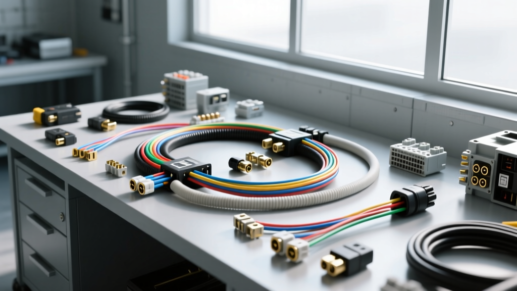
The Hidden Risks of Improper P&A Auto Electric Installations
When sourcing replacement electrical components, dealership Parts & Accessories (P&A) departments supply OEM-grade wiring harnesses, telematics modules, and auxiliary lighting kits. While these P&A auto electric components are engineered to exact factory specifications, the physical installation process is where catastrophic failures occur. Junior technicians and DIY enthusiasts often assume that because a P&A kit is 'OEM,' it is entirely plug-and-play. This assumption leads to ignored pin tensions, misrouted harnesses, and overloaded Body Control Module (BCM) circuits.
This guide details the critical safety warnings and the most common technical mistakes made when integrating P&A auto electric parts into modern vehicle architectures, ensuring your installations meet SAE and OEM standards.
Critical Safety Warnings Before Touching the Harness
SRS and Airbag Circuit Protocols
Many P&A accessory kits, such as OEM seat heaters or steering wheel control modules, integrate near or through the Supplemental Restraint System (SRS) harness. SRS connectors are universally color-coded yellow and feature internal shorting bars designed to prevent accidental airbag deployment when disconnected.
- Never use a test light or standard multimeter probes on SRS circuits. The internal battery in a multimeter or the current from a test light can provide enough milliamps to ignite the squib in an airbag or seatbelt pretensioner.
- Capacitor Discharge: After disconnecting the 12V battery, wait a minimum of 15 minutes (or up to 30 minutes on late-model luxury vehicles) to allow the SRS backup capacitors to discharge before working near yellow P&A connectors.
Battery Disconnect and Terminal Torque
Failing to properly disconnect and reconnect the battery leads to voltage spikes that can fry sensitive P&A telematics modules. When reconnecting, adhere strictly to OEM torque specifications. For example, GM side-post battery terminals require exactly 12 to 15 Nm (106 to 133 in-lbs) of torque. Over-tightening cracks the internal lead bushing, causing acid leaks and high-resistance hot spots that mimic a failing alternator.
Top 4 Mistakes When Installing P&A Electrical Components
Mistake 1: Destroying Pin Tension with Multimeter Probes
The most common mistake when diagnosing a newly installed P&A auto electric harness is testing female terminals with standard multimeter probes. Connectors like the Delphi Aptiv Metripack 150 or 280 series rely on precise spring-finger tension to maintain a gas-tight connection. A standard Fluke multimeter probe is often tapered and wider than the mating male pin. Forcing the probe into a female Metripack 150 terminal spreads the internal spring fingers. When the harness is reconnected, the loose terminal causes micro-arcing, localized melting, and intermittent sensor failures under vibration (terminal fretting).
The Fix: Always use dedicated, straight male test pins of the correct width (e.g., 1.5mm for Metripack 150) to back-probe or test terminal tension. If a terminal feels loose, it must be replaced using the correct crimp die, not merely squeezed with pliers.
Mistake 2: Ignoring CAN-Bus Termination Resistors
P&A auto electric kits often include fleet tracking, telematics, or auxiliary display modules that communicate via the High-Speed CAN network (CAN-C or GMLAN). A standard CAN-bus requires exactly two 120-ohm termination resistors at the extreme ends of the network, creating a parallel resistance of 60 ohms.
If a technician splices a P&A module that contains an internal 120-ohm resistor into the middle of the CAN-bus, the network resistance drops to approximately 40 ohms. The BCM will immediately detect this impedance mismatch, throw a U0001 (High Speed CAN Communication Bus) code, and potentially shut down the entire network, disabling the ABS and power steering.
The Fix: Always measure CAN-H and CAN-L resistance with the battery disconnected before and after installing P&A network modules. If the P&A module has internal termination, ensure it is installed at the physical end of the bus topology, or disable the internal resistor if splicing into a mid-node.
Mistake 3: Overloading BCM-Controlled Accessory Feeds
Many P&A accessory kits (like OEM bed lighting or running board LEDs) come with 18 AWG pigtails designed to tap into existing parking light or cargo lamp circuits. Technicians often assume that because the P&A kit includes an inline 15A fuse, the vehicle's factory wiring can handle the load. However, modern vehicles use the BCM to pulse-width modulate (PWM) or switch low-current circuits. Tapping a 10A LED light bar into an 18 AWG (0.8 mm²) BCM-controlled circuit that is only rated for 2A will destroy the BCM's internal solid-state driver transistor.
The Fix: Use the P&A harness only as a signal trigger. Connect the 18 AWG P&A trigger wire to a 30A automotive relay coil, and power the relay's switched side directly from the battery using a dedicated 12 AWG wire with an inline fuse.
Mistake 4: Misapplying Dielectric Grease
Technicians frequently pack P&A auto electric connectors with silicone dielectric grease, mistakenly believing it improves conductivity. Dielectric grease is an insulator. If packed inside the terminal cavity, it blocks the metal-to-metal contact, causing high resistance and voltage drops. Dielectric grease should only be applied to the outer plastic housing seals and wire grommets to prevent moisture ingress.
P&A Auto Electric Connector & Wire Specification Chart
When repairing or extending P&A harnesses, you must match the exact terminal and wire specifications. Refer to the SAE J1128 standard for low-tension primary cable requirements.
| Connector Series | Terminal Width | Wire Range (AWG) | Max Current per Pin | Typical P&A Application |
|---|---|---|---|---|
| Metripack 150 | 1.5 mm | 22 - 18 AWG | 15 Amps | Sensors, Injectors, Low-draw LED triggers |
| Metripack 280 | 2.8 mm | 20 - 14 AWG | 20 Amps | Blower motors, Solenoids, Horn relays |
| Metripack 630 | 6.3 mm | 12 - 10 AWG | 30 Amps | ABS pump feeds, High-draw P&A winch solenoids |
| Deutsch DT | 1.59 mm | 20 - 16 AWG | 13 Amps | Off-road aux lighting, Marine P&A accessories |
Troubleshooting Post-Installation Voltage Drops
After installing any P&A auto electric harness, perform a dynamic voltage drop test to verify the integrity of your connections. According to ASE Electrical Testing Guidelines, a healthy connection should exhibit minimal resistance.
- Set your multimeter to DC Volts.
- Place the red probe on the positive battery post and the black probe on the component's positive input pin.
- Activate the circuit (e.g., turn on the P&A auxiliary lights).
- Read the voltage: A reading above 0.1V across a single connector indicates terminal fretting, corrosion, or insufficient pin tension. A reading above 0.5V on the total positive feed indicates an undersized wire or a failing crimp.
- Repeat on the ground side: Place the red probe on the component's ground pin and the black probe on the negative battery post. Any reading over 0.1V requires cleaning the chassis ground ring terminal and verifying the star-washer is biting into bare metal, not paint or powder coat.
Authoritative References & Further Reading
To ensure your P&A auto electric installations remain safe and compliant, consult the following industry standards:
- SAE J1128: Defines the thermal and physical requirements for low-tension primary automotive cables (GXL, TXL, SXL insulation types). Read SAE J1128 Standards.
- SAE J1292: Covers automobile electrical systems, including routing guidelines to prevent EMI interference and thermal degradation near exhaust manifolds. Read SAE J1292 Standards.
- ASE (National Institute for Automotive Service Excellence): Provides the foundational testing procedures for voltage drop, pin tension, and CAN-bus diagnostics utilized by certified master technicians. Visit ASE.
By respecting the engineering behind P&A auto electric components and adhering to strict terminal and routing protocols, you eliminate the risk of parasitic draws, BCM failures, and catastrophic electrical fires.