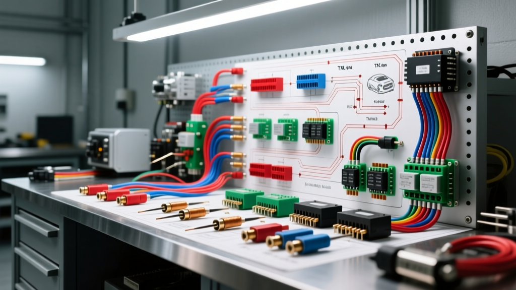
The Benchmark of Custom Harness Fabrication
When master technicians, restomod builders, and motorsport engineers reference the gold standard in bespoke vehicle electrical architecture, the methodologies pioneered by elite fabrication hubs like Ken's Auto Electric frequently emerge as the benchmark. Building a custom wiring harness for a high-horsepower EFI restomod, a dedicated track car, or a complex overland rig requires moving far beyond generic bulk-wire kits and plug-and-play universal looms. It demands an advanced understanding of voltage drop calculations, inductive kickback suppression, CAN-bus topology, and marine-grade environmental sealing. This advanced technical deep dive deconstructs the wiring principles, relay logic topologies, and termination standards that define top-tier custom auto electrical work, providing actionable specifications for high-stakes automotive builds.
Conductor Metallurgy and Insulation Thermodynamics
The foundation of any reliable harness is the conductor and its dielectric insulation. Standard PVC-jacketed wire (SAE J1128 Type GPT) is entirely inadequate for high-heat zones such as engine bays, exhaust tunnels, or turbocharger enclosures. The Ken's Auto Electric methodology mandates the use of Cross-Linked Polyethylene (XLPE) insulated cables, specifically TXL, GXL, or SXL classifications. TXL (Thin-wall) is the preferred choice for modern harnesses due to its high temperature resistance (up to 155°C) and reduced outer diameter, which allows for tighter bend radii and lighter overall harness weight without sacrificing current-carrying capacity.
| AWG Size | Cross-Section (mm²) | Insulation Type | Max Continuous Amps (Chassis) | Resistance (mΩ/ft @ 20°C) |
|---|---|---|---|---|
| 18 AWG | 0.80 | TXL | 6A | 6.51 |
| 14 AWG | 2.00 | TXL | 15A | 2.58 |
| 10 AWG | 5.26 | TXL | 30A | 1.02 |
| 8 AWG | 8.37 | GXL | 40A | 0.64 |
| 4 AWG | 21.15 | SXL | 100A | 0.25 |
For high-amperage circuits like electric power steering (EPS) pumps or dual cooling fan arrays, calculating voltage drop is critical. A 10-foot run of 10 AWG wire carrying 30 amps will experience a voltage drop of approximately 0.3V. While acceptable for a cooling fan, this drop is catastrophic for an EFI fuel pump relay feed, where the ECU expects a stable 13.8V to maintain consistent injector duty cycles. In these scenarios, upsizing to 8 AWG or utilizing a dedicated rear-mounted power distribution block is mandatory.
Advanced Relay Logic and Inductive Suppression
Electromechanical relays remain the workhorses of automotive power distribution, but improper implementation leads to ECU driver burnout and electromagnetic interference (EMI). Standard ISO mini relays (Bosch-style 5-pin) utilize a coil resistance of roughly 70 ohms, drawing about 170mA of current. When the ECU's low-side driver grounds Pin 85 to energize the coil (Pin 86 connected to 12V), the magnetic field collapses instantly upon de-energization. This collapse generates a high-voltage inductive spike (often exceeding 100V) that will arc across the relay contacts or destroy the ECU's internal transistor.
Flyback Diode Integration
To suppress this inductive kickback, elite harness builders integrate flyback diodes directly into the relay socket or harness breakout. A standard 1N4007 rectifier diode is wired in reverse bias across the coil pins (cathode to Pin 86/12V, anode to Pin 85/ECU Ground). This provides a safe recirculation path for the collapsing magnetic field, clamping the voltage spike to less than 1V. For solid-state relay (SSR) applications driven by PWM fan controllers, opto-isolated drivers are utilized to completely separate the high-amperage load circuit from the delicate 5V logic signals of the engine management system.
Troubleshooting Relay Chatter and ECU Burnout
- Symptom: Rapid relay clicking (chatter) under load.
- Cause: Voltage drop on the coil ground circuit causing the coil to de-energize when the high-amperage contacts (Pin 30 to 87) close and draw heavy current, dropping system voltage below the relay's 9V drop-out threshold.
- Fix: Route the relay coil ground (Pin 85) directly to the ECU sensor ground or a dedicated clean ground bus, completely isolated from the high-amperage load ground.
Environmental Termination: Deutsch DT vs. Metri-Pack
The termination point is the most common failure node in any automotive electrical system. Vibration, thermal cycling, and capillary action wicking moisture into the wire strands cause catastrophic high-resistance faults. The industry standard for harsh environments is the TE Connectivity Deutsch DT Series and the Delphi Metri-Pack 2.8 series. Unlike standard crimp connections, these systems utilize a multi-finger beryllium copper contact coupled with a secondary silicone wedgelock (DTM/DT series) to prevent contact back-out under severe vibration.
| Connector Series | Cavity Size / AWG Range | Required Crimp Tool | Min. Pull-Out Force | Sealing Method |
|---|---|---|---|---|
| Deutsch DT | Size 16 (14-18 AWG) | DT-XT-001 / M22520 | 15 lbs (67 N) | Silicone Wedgelock + Rear Grommet |
| Metri-Pack 2.8 | 2.8mm (10-14 AWG) | Delphi Hand Crimper | 20 lbs (89 N) | Primary Silicone Ribbed Seal |
| Weather-Pack | Tower (10-14 AWG) | HT-279 / M22520 | 12 lbs (53 N) | Cylindrical Silicone Plug |
Proper crimping requires a four-indent, closed-barrel crimp tool (such as the M22520/2-01). Open-barrel crimps (F-style) are strictly prohibited in high-vibration engine bay applications. Furthermore, all environmental terminations must be sealed using dual-wall, adhesive-lined polyolefin heat shrink (e.g., 3M FP-301 or equivalent). The inner meltable adhesive layer flows into the wire strands during heating, creating a hermetic seal that prevents oxygen and moisture from causing galvanic corrosion at the crimp barrel.
Ground Plane Architecture and Millivolt Drop Testing
A vehicle's chassis is not a perfect conductor; it is a massive, albeit flawed, resistor. Relying on the chassis for high-amperage return paths (daisy-chaining grounds) introduces ground loops, alternator whine in audio systems, and erratic sensor readings. The advanced approach dictates a 'Star Grounding' architecture. In this topology, a central, isolated ground bus bar is mounted to the chassis using a massive 1/0 AWG battery cable. All individual circuit grounds (EFI injectors, ignition coils, sensor shields) terminate at this single bus bar via dedicated 14 AWG or 12 AWG wires.
Validating Ground Integrity
Torque specifications for ground studs are critical. An M8 stainless steel ground stud securing a 1/0 AWG lug to a bare-metal chassis point must be torqued to exactly 20 Nm (15 lb-ft) using a star washer to bite through any residual primer or powder coat. Validation is performed via a millivolt drop test under load. With the circuit energized (e.g., cooling fans running at 100% PWM duty cycle), a digital multimeter set to DC millivolts is placed with the positive probe on the battery negative terminal and the negative probe on the component's ground casing. A reading exceeding 50mV (0.050V) indicates excessive resistance, requiring immediate surface preparation, lug upsizing, or the addition of a parallel ground strap. By adhering to these rigorous standards, builders ensure that the electrical architecture is as robust and reliable as the mechanical drivetrain it supports.