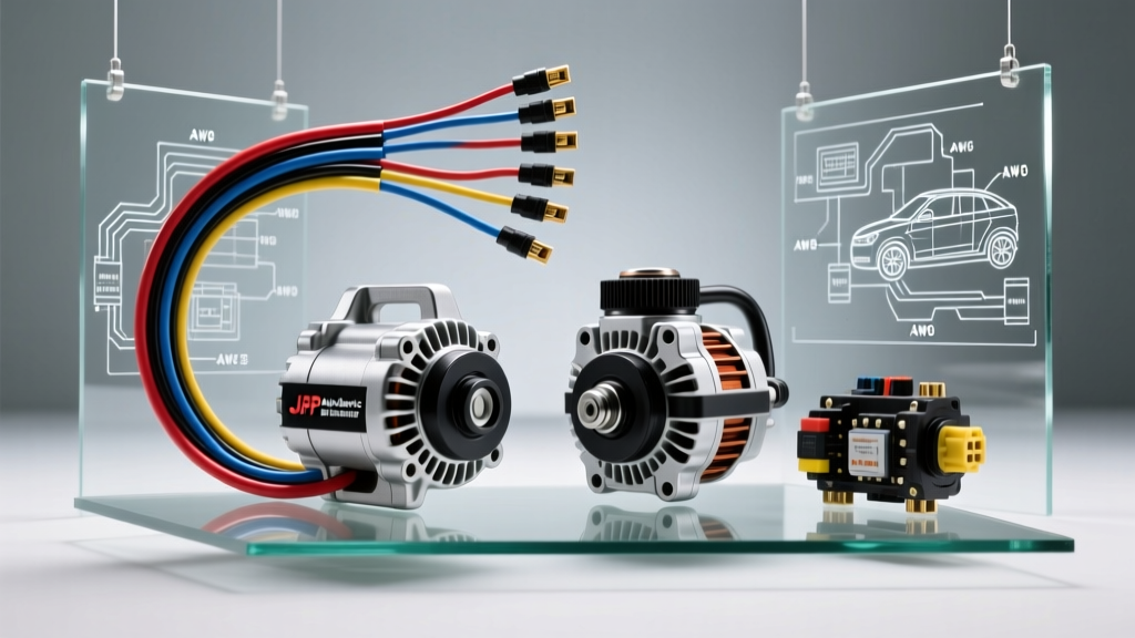
Evaluating J&P Auto Electric Components vs. OEM Replacements
When building a custom hot rod, outfitting an off-road rig with high-draw accessories, or simply replacing failing factory components, selecting the right electrical hardware is critical. J&P Auto Electric has carved out a niche by supplying high-output alternators, heavy-duty gear-reduction starters, and custom wiring pigtails that bridge the gap between standard OEM replacements and ultra-expensive boutique racing components. This selection guide compares J&P Auto Electric offerings against standard factory equipment, providing the exact wiring specifications, AWG requirements, and pinout configurations needed for a reliable installation.
High-Output Alternator Selection and Wiring Upgrades
Standard OEM alternators, such as the ubiquitous GM CS130 (105A) or Ford 3G (95A), are designed to run factory lighting, basic HVAC, and stock ECU systems. However, adding off-road LED light bars, massive winches, or high-wattage car audio systems quickly overwhelms these units. J&P Auto Electric offers upgraded CS144 and large-case 3G alternatives pushing 200A to 250A. While the physical mounting ears often match OEM, the electrical infrastructure must be upgraded to handle the increased current.
GM CS130 / CS144 4-Pin Connector Pinout
When upgrading to a high-amp J&P Auto Electric GM-style alternator, you must correctly wire the 4-pin regulator connector. Miswiring this plug is the leading cause of overcharging and fried PCM modules.
- Terminal P (Phase): Connects to the stator winding. Used by the internal regulator to monitor alternator RPM. Often left unconnected in early aftermarket swaps, but required for proper PWM signaling in modern J&P units.
- Terminal F (Field): Pulse Width Modulated (PWM) signal to the PCM. On older carbureted swaps, this is left disconnected or tied to a 12V ignition source via a 10k-ohm resistor to prevent dash warning lights.
- Terminal L (Lamp): Connects to the dashboard charge indicator light. The regulator grounds this circuit when the alternator is not producing voltage. Use a 14 AWG wire with a 194 bulb in the circuit to provide initial excitation current.
- Terminal S (Sense): The most critical wire. This must be routed directly to the positive battery terminal or the main distribution block to read true system voltage. Never jumper 'S' to the alternator output post, or voltage drop across the charge wire will cause the regulator to overcharge the battery.
Alternator Output vs. Minimum Wire Gauge Chart
According to the SAE J1128 Low Tension Primary Cable Standard, wire gauge must be selected based on continuous amperage load and wire length. Factory 10 AWG charge wires will melt and cause an engine bay fire when paired with a 220A alternator. Use the following chart when installing J&P Auto Electric high-output units:
| Alternator Output | Main Charge Wire (AWG) | Mega Fuse Rating | Ground Strap (AWG) |
|---|---|---|---|
| 100A - 120A (OEM) | 8 AWG | 150A | 8 AWG |
| 140A - 170A | 6 AWG | 200A | 6 AWG |
| 200A - 220A | 4 AWG | 250A | 4 AWG |
| 250A+ | 2 AWG or 1/0 AWG | 300A | 2 AWG |
For deeper technical insights on alternator wiring and sense circuits, refer to the Mad Electrical Tech Guide on Alternators, which remains an industry-standard reference for custom automotive charging systems.
Heavy-Duty Starter Motors and Solenoid Circuits
OEM starters are designed for stock compression ratios and standard parasitic drag. When dealing with high-compression engines, stiff accessory drives, or extreme under-hood heat, OEM starters suffer from heat soak and voltage drop. J&P Auto Electric supplies permanent-magnet, gear-reduction (PMGR) mini starters. These units draw significantly fewer amps (often 40% less) while producing 30-50% more cranking torque compared to traditional direct-drive OEM starters.
The Starter Solenoid Voltage Drop Problem
The most common failure mode when installing a new aftermarket starter is a 'single click' no-crank condition. This is rarely a defective starter; it is almost always a voltage drop issue on the solenoid trigger wire. The factory ignition switch routes 12V through the steering column, down to the neutral safety switch, and back to the starter solenoid 'S' terminal. By the time that signal reaches the starter, it may have dropped to 8V or 9V due to aging copper and corroded bulkhead connectors. The J&P PMGR solenoid requires a solid 11.5V+ to fully engage the heavy-duty contactor.
The 40A Bosch-Style Relay Upgrade
To guarantee full battery voltage reaches the J&P Auto Electric starter solenoid, bypass the factory trigger wire using a standard 4-pin Bosch-style relay. This is a mandatory upgrade for any high-performance or classic car wiring harness.
- Pin 86 (Coil +): Connect to the factory ignition switch 'Start' wire (usually 14 AWG Pink or Yellow). This wire only needs to carry 0.5A to trigger the relay.
- Pin 85 (Coil -): Connect to a clean chassis ground using 14 AWG Black wire.
- Pin 30 (Common / Input): Connect directly to the battery positive terminal or the main starter lug via a 40A inline fuse. Use 10 AWG Red wire.
- Pin 87 (Normally Open / Output): Connect to the 'S' terminal on the J&P starter solenoid using 12 AWG Purple wire.
This configuration ensures that the starter solenoid receives full, unimpeded battery voltage the moment the key is turned, eliminating heat-soak starting issues entirely.
Termination Best Practices and Real-World Troubleshooting
Even the highest quality J&P Auto Electric components will fail if the wiring terminations are compromised. High-amp circuits generate immense heat at points of high resistance.
Crimping vs. Soldering High-Amp Connections
Never use solder-only connections for the main charge wire or starter feed cables. Solder is brittle and will fracture under the constant vibration of an internal combustion engine, leading to arcing and fire. Furthermore, solder wicks up into the wire strands under heat, creating a solid block that cannot flex. Always use a closed-barrel, adhesive-lined heat-shrink crimp terminal applied with a hydraulic or heavy-duty mechanical crimping tool. The adhesive lining seals out moisture, preventing the green corrosion (copper oxide) that drastically increases electrical resistance.
Troubleshooting Decision Tree
- Symptom: Alternator whine in the audio system that changes pitch with engine RPM.
Cause: Poor alternator grounding or the 'Sense' wire is reading voltage at the alternator post instead of the battery.
Fix: Add a dedicated 4 AWG ground strap from the alternator case to the engine block, and reroute the Sense wire directly to the positive battery terminal. - Symptom: Starter clicks once, dashboard lights dim, but engine does not crank.
Cause: High resistance on the main battery feed cable or a failing battery ground strap.
Fix: Perform a voltage drop test across the positive cable and the ground strap during a crank attempt. Any reading over 0.2V indicates a faulty cable or corroded terminal. - Symptom: Battery overcharges at 15.5V+ and boils acid.
Cause: The 'S' (Sense) terminal on the alternator pigtail is broken, disconnected, or has a blown inline fuse.
Fix: Check continuity from the alternator 'S' pin to the battery positive post. Replace the pigtail if the internal copper strands are fractured.
Final Selection Verdict
J&P Auto Electric provides an excellent middle-ground for builders who need more amperage and cranking torque than OEM parts can provide, without paying the premium of fully bespoke racing components. By pairing their high-output alternators and PMGR starters with properly sized AWG cabling, dedicated sense wires, and solenoid trigger relays, you ensure a robust, reliable electrical architecture capable of handling modern automotive accessory loads.