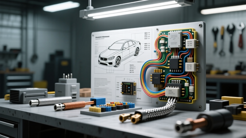
The Benchmark for Safety: Wayne Parker's Auto Electric Standards
Modern vehicle electrical architecture is a complex network of high-amperage power circuits, sensitive CAN bus data lines, and pulse-width modulated (PWM) sensors. When modifying or repairing these systems, amateur mistakes can lead to catastrophic failures, ECU damage, or vehicle fires. In the professional diagnostic community, the rigorous protocols championed by Wayne Parker's Auto Electric have become a gold-standard benchmark for identifying, preventing, and correcting wiring hazards. By analyzing the most frequent failures seen in bays that ignore these standards, we can establish a definitive guide to auto electrical safety and common mistakes.
Whether you are installing an aftermarket electric fuel pump, upgrading a charging system, or integrating auxiliary lighting, understanding the physics of 12-volt systems and the strict requirements of automotive-grade connectivity is non-negotiable. Below, we break down the most dangerous wiring mistakes and provide the expert-level corrections required to meet top-tier safety standards.
Mistake #1: Ignoring AWG Limits and Voltage Drop Calculations
One of the most pervasive and dangerous errors in 12-volt systems is selecting wire gauge based on physical fitment rather than current-carrying capacity. A common scenario involves installing a 40-amp dual cooling fan relay kit and routing 14 AWG wire because it easily slides into the provided spade terminals. This is a severe fire hazard.
According to SAE J1128 standards for low-tension primary cable, wire gauge must be calculated based on maximum continuous amperage and the total length of the circuit to account for voltage drop. A 14 AWG wire rated for 15 amps will rapidly overheat, melt its PVC or cross-linked polyethylene (XLPE) insulation, and potentially ignite surrounding materials when subjected to a 40-amp continuous load.
Voltage Drop & AWG Specification Chart (12V System)
| Wire Gauge (AWG) | Max Continuous Amps | Max Length (One Way) for <3% Drop @ Max Amps | Common Application |
|---|---|---|---|
| 18 AWG | 5A | 12 feet | ECU sensors, 5V reference, LED indicators |
| 16 AWG | 10A | 15 feet | Horn relays, interior lighting, radio memory |
| 14 AWG | 15A | 18 feet | Fuel injectors, single cooling fan, headlights |
| 12 AWG | 20A | 20 feet | Power windows, seat heaters, auxiliary 12V sockets |
| 10 AWG | 30A | 22 feet | Ignition feed, ABS module power, electric fuel pumps |
| 8 AWG | 50A | 25 feet | High-output alternator charging lines, winch feeds |
| 4 AWG | 100A+ | 30 feet | Main battery cables, starter motor circuits |
The Correction: Always calculate the total circuit length (positive + ground return) and use a voltage drop calculator. For high-amperage engine bay applications, always use SAE-rated GXL or TXL wire, which features thin-wall, high-temperature XLPE insulation capable of withstanding under-hood ambient temperatures up to 125°C.
Mistake #2: Soldering in High-Vibration Environments
Many DIYers and novice technicians believe that soldering wires together and covering them with heat shrink is the ultimate, waterproof connection. In an automotive environment, this is fundamentally incorrect. Solder creates a rigid, brittle joint. When subjected to the constant harmonic vibration of a chassis or engine block, the boundary between the flexible wire and the rigid solder blob becomes a stress riser. Over time, the copper strands fatigue and snap inside the insulation, creating an intermittent open circuit or high-resistance arc.
Furthermore, solder relies on capillary action. If flux is not completely cleaned, it becomes corrosive over time, eating away at the copper strands beneath the heat shrink—a phenomenon known as "green death."
The Correction: Professional shops adhering to Wayne Parker's Auto Electric methodologies exclusively use mechanical, open-barrel crimps. For engine bay and chassis connections, use Aptiv (formerly Delphi) Metri-Pack 280 series or Weather-Pack terminals. These terminals feature a copper-alloy open barrel that is crimped using a specialized ratcheting tool, creating a cold-weld that is both gas-tight and vibration-resistant. For heavy-duty applications, Deutsch DT solid-copper crimp barrels with dual-seal silicone plugs are the industry standard.
Mistake #3: Grounding to Painted Sheet Metal
Approximately 80% of all automotive electrical "gremlins"—from dimming headlights to erratic transmission shifting—are rooted in poor ground connections. A common mistake is attaching a 10 AWG ground wire with a standard ring terminal directly to a painted or powder-coated chassis component, or using a self-tapping screw into thin sheet metal.
Paint, undercoating, and rust are insulators. Relying on the threads of a screw to bite through the paint to establish a ground path introduces massive electrical resistance. This resistance forces the current to seek alternative paths to ground, often back-feeding through sensitive ECU ground planes or CAN bus shields.
Proper Grounding Protocol
- Surface Prep: Use a 3M Roloc disc or sandpaper to remove all paint, rust, and sealant down to bare, shiny metal.
- Terminal Selection: Use a non-insulated, brazed-seam ring terminal sized exactly to the stud (e.g., a 5/16" terminal for a 5/16" bolt). Never force a smaller terminal over a larger stud by bending the copper.
- Hardware: Use a steel star washer between the ring terminal and the bare metal to bite into the chassis, followed by a flat washer and a zinc-plated hex nut or bolt. Apply a dab of dielectric grease over the completed terminal to prevent oxidation, but never apply grease between the terminal and the bare metal surface.
Mistake #4: Splicing into CAN Bus Data Lines
With the advent of OBD-II and multiplexed networks, vehicles rely on Controller Area Network (CAN) bus systems to transmit critical data between modules. A disastrous mistake made by alarm and remote-start installers is splicing into CAN-High and CAN-Low wires using standard T-taps or twisting them together with solder.
The CAN bus operates as a differential twisted-pair network. The physical twisting of the wires (typically 1 twist per inch) is engineered to cancel out electromagnetic interference (EMI). Furthermore, the network relies on a precise 120-ohm impedance, maintained by terminating resistors located at the ends of the bus (often inside the ECU and the instrument cluster).
The Danger: Untwisting the wires to splice into them destroys the noise-canceling geometry. Introducing a T-tap adds parasitic capacitance and alters the impedance. This results in signal reflection, data packet collisions, and the throwing of U-codes (e.g., U0100 - Lost Communication with ECM). In modern vehicles with drive-by-wire throttle and electric power steering, CAN bus corruption can lead to sudden loss of vehicle control.
The Correction: Never use T-taps or scotch-locks on data lines. If a CAN bus connection is absolutely necessary (e.g., for a telematics or fleet tracking module), use a proper CAN bus breakout harness or splice using a high-impedance, non-intrusive capacitive coupling module. Always verify the OBD-II Data Link Connector (DLC) Pin 6 (CAN-H) and Pin 14 (CAN-L) with an oscilloscope to ensure the differential voltage remains within the 2.5V to 3.5V operating window.
Mistake #5: Omitting Flyback Diodes on Relay Coils
When wiring auxiliary components like nitrous solenoids, water/methanol injection pumps, or heavy-duty lighting contactors, technicians often wire a standard 4-pin ISO relay directly to an ECU driver or a sensitive dashboard switch. When the switch is opened, the magnetic field in the relay coil collapses, generating a reverse-voltage spike (flyback voltage) that can exceed 100 volts.
This spike will instantly fry the delicate internal transistor of an ECU driver circuit or melt the contacts of a low-amperage dashboard switch.
The Correction: Always install a flyback suppression diode (such as a 1N4001 or 1N4004) across the relay coil terminals (Pins 85 and 86). The diode must be installed in reverse bias (the silver stripe facing the positive 12V trigger source). This provides a safe recirculation path for the collapsing magnetic field, clamping the voltage spike to a harmless ~0.7V and protecting your vehicle's expensive control modules.
Summary: Respect the Architecture
Automotive electrical systems demand respect for physics, material science, and network topology. The safety warnings and diagnostic standards upheld by Wayne Parker's Auto Electric serve as a vital reminder that there are no shortcuts in 12-volt architecture. By adhering to SAE wire specifications, utilizing proper open-barrel crimps, engineering flawless bare-metal grounds, protecting data lines, and suppressing inductive spikes, you ensure the reliability, safety, and longevity of the vehicle's electrical ecosystem.