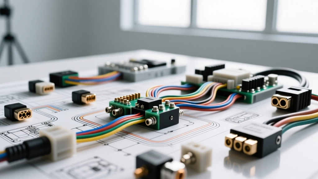
The Professional Standard in Auto Electrical Selection
When diagnosing complex charging and cranking systems, the longevity of the repair is entirely dependent on the quality of the replacement components. Master technicians and specialized regional facilities, such as the benchmark set by Allentown Auto Electric LLC, rely on strict product comparison matrices to select between Original Equipment Manufacturer (OEM), remanufactured, and aftermarket electrical parts. Selecting the wrong alternator or starter motor can lead to parasitic draws, voltage regulator failure, and melted charge wires.
This guide breaks down the technical specifications, wiring requirements, and diagnostic standards used by top-tier auto electric shops to evaluate and select the correct electrical components for modern and legacy vehicle architectures.
Alternator Architecture: OEM vs. Remanufactured vs. Aftermarket
The alternator is the heart of the vehicle's electrical system. When comparing units, professionals evaluate the stator winding quality, diode rectifier heat tolerance, and voltage regulator logic. The Delco Remy CS130D and AD244 series remain industry standards for comparison.
Voltage Regulator Pinouts and Wiring Logic
Modern internally regulated alternators utilize specific pin configurations to communicate with the Powertrain Control Module (PCM). A common failure point in cheap aftermarket units is the misconfiguration of the 4-pin regulator connector.
- Terminal L (Lamp): Provides a ground path to illuminate the dashboard battery light. Requires a 560-ohm resistor in parallel to prevent bulb burnout.
- Terminal I (Ignition): Receives 12V from the ignition switch to wake the regulator.
- Terminal F (Field): PWM (Pulse Width Modulated) signal sent to the PCM to indicate alternator load and field duty cycle.
- Terminal P (Phase): Reads the AC ripple from the stator to verify rotor rotation and diode health.
Alternator Charge Wire Sizing Specifications
Upgrading from a 100A to a 140A+ alternator requires immediate attention to the main charge wire. Using undersized wire causes voltage drop and thermal degradation of the insulation. According to SAE J1128 standards for low-tension primary cable, the following AWG sizes must be used for alternator output circuits:
| Alternator Output (Amps) | Minimum Wire Gauge (AWG) | Max Run Length (Inches) | Ring Terminal Size |
|---|---|---|---|
| 80A - 100A | 8 AWG | 36" | 5/16" or M8 |
| 105A - 120A | 6 AWG | 48" | 5/16" or M8 |
| 130A - 150A | 4 AWG | 60" | 3/8" or M10 |
| 160A - 200A+ | 2 AWG or 1/0 AWG | 72" | 3/8" or M10 |
Starter Motor Circuits and Solenoid Relays
When comparing starter motors, the primary distinction is between Direct Drive and Permanent Magnet Gear Reduction (PMGR) designs. PMGR starters, widely adopted by OEMs since the late 1990s, use a planetary gear set to multiply torque while drawing 30% less amperage from the battery. Remanufactured PMGR units must be scrutinized for proper armature clearance and solenoid throw-out lever engagement.
ISO Relay Pin Configuration for Starter Circuits
Modern starter circuits utilize an ISO mini relay to protect the ignition switch from the high inrush current of the starter solenoid pull-in coil. When diagnosing a no-crank condition, verifying the relay pinout is critical:
- Pin 30 (Common): Fused 12V battery feed (typically 30A or 40A).
- Pin 87 (Normally Open): Output to the starter solenoid 'S' terminal.
- Pin 85 (Coil Ground): Grounded via the PCM or neutral safety switch.
- Pin 86 (Coil Power): 12V ignition start signal.
Top shops like Allentown Auto Electric LLC mandate that the starter control circuit (Pin 87 to Solenoid S) utilize a minimum of 12 AWG wire to prevent voltage drop across the relay contacts, which can result in a weak solenoid engagement and solenoid contact welding.
Wiring Harness Materials and Connector Selection
The selection of wiring and connectors separates a permanent repair from a recurring electrical fault. The comparison between standard PVC wire and Cross-Linked Polyethylene (XLPE) wire is a critical factor in engine bay environments.
SAE J1128 Wire Insulation Comparison
| Wire Type | Insulation Material | Max Temp Rating | Wall Thickness | Best Application |
|---|---|---|---|---|
| GPT | PVC | 105°C | Standard | Cabin wiring, low-heat zones |
| GXL | XLPE | 125°C | Thin | Engine bay harnesses, OEM standard |
| TXL | XLPE | 125°C | Extra Thin | Tight conduit routing, high-density connectors |
Using GPT (PVC) wire in an engine bay near exhaust manifolds will result in insulation melting and short circuits. Professional electrical shops exclusively stock GXL and TXL wire for under-hood repairs.
Connector Selection: Metri-Pack vs. Deutsch DT
For sensor and actuator connections, the physical connector determines moisture ingress resistance.
- Weather-Pack / Metri-Pack 280: Standard for GM and Ford body control modules and interior sensors. Features a silicone ribbed seal but is prone to terminal fretting corrosion if dielectric grease is omitted.
- Deutsch DT Series: The heavy-duty standard for high-vibration, high-moisture environments (e.g., cooling fan relays, transmission solenoids). Utilizes a solid silicone boot and secondary wedge locks to prevent terminal back-out.
When rebuilding custom harnesses, upgrading critical under-carriage connections from Metri-Pack to Deutsch DT is a recommended best practice for long-term reliability.
Diagnostic Benchmarks and Voltage Drop Limits
Component selection is only half the battle; verifying the circuit's ability to support the new component is the hallmark of a professional facility. According to Bosch Automotive Electrics diagnostic procedures, voltage drop testing is mandatory after any starter or alternator installation.
Maximum Allowable Voltage Drop Specifications
| Circuit Under Test | Test Condition | Max Allowable Drop (DC Volts) |
|---|---|---|
| Battery Positive to Starter B+ Terminal | Cranking Engine | 0.50V |
| Starter Housing to Battery Negative | Cranking Engine | 0.20V |
| Alternator B+ to Battery Positive | Engine at 2000 RPM, Loads ON | 0.30V |
| Alternator Case to Battery Negative | Engine at 2000 RPM, Loads ON | 0.10V |
| PCM Sensor Ground to Battery Negative | Key ON, Engine OFF | 0.05V (50mV) |
If the voltage drop from the alternator B+ terminal to the battery positive post exceeds 0.30V under load, the charge wire or battery terminals must be replaced, regardless of whether an OEM or aftermarket alternator was installed. High resistance on the ground side of the alternator case will also cause the internal voltage regulator to overcompensate, leading to premature diode failure.
Conclusion
Selecting the correct auto electrical components requires a deep understanding of circuit architecture, wire gauge ampacity, and environmental tolerances. By applying the rigorous comparison standards utilized by experts like Allentown Auto Electric LLC, technicians and DIYers can avoid the pitfalls of inferior aftermarket parts. Always verify OEM pinouts, adhere to SAE wiring standards, and perform strict voltage drop testing to ensure the electrical system operates within factory specifications.